FCM/A5, FEV, FJM, FEM4, FHMA5, FMA4/5, FM(C,U)5, FS(A,M,U)4, FTMA5, F(V,X)M4, F5M4, REM4, WA(H,M,P,X) WB(G,H)L, WC(G,H)L: Service and Maintenance
Manufacturer reserves the right to change, at any time, specifications and designs without notice and without obligations.
4
(1.) Check low-voltage transformer leads R (red) and C
(brown). Make sure they are wired to correct location. The
unit will not function without proper connections.
(1.) Check output voltage of transformer secondary side R (red)
and C (brown). If transformer output is low (less than
18VAC), refer to items 3 and 4 of previous “IF
TRANSFORMER HAS HIGH VOLTAGE APPLIED TO
IT” section.
• IF TRACES ARE OVERHEATED ON BACK OF PCB:
Usually whenever a trace is blown on PCB, it means either there
has been a high-voltage short or high voltage has been applied to
low-voltage circuit. This can be prevented by making sure PCB is
wired correctly before PCB has power applied to it.
• If Transformer Fuse Keeps Blowing:
When low-voltage fuse blows, it means transformer would have
blown if fuse had not been in circuit to protect it. The fuse usually
blows when there is a high current draw on transformer, high
voltage applied to low-voltage circuit, or a direct secondary short.
When there is a high current draw on transformer, it is most likely
because transformer has been shorted or system is trying to draw
more VA than transformer rating allows. When fuse blows because
of high voltage, the system has mixed high- and low-voltage
signals.
(1.) Check wiring of sequencers/relays as shown in Fig. 1 and
Fig. 2. Be sure transformer is not shorting out because
thermostat wires are miswired.
(1.) Check wiring of relays as shown in Fig. 1 and Fig. 2. Be
sure low-voltage and high-voltage wiring is correct.
(1.) Check VA draw on transformer. If VA draw is more than VA
rating of transformer, fuse will blow. If this is the case,
replace transformer with one that has a higher VA rating and
meets system specifications.
If Fan Runs Continuously:
(1.) If PCB has no low-voltage power, check blue and black fan
leads. These may be switched at sequencer/relay.
(1.) If PCB has low-voltage power, check fan relay to see if it is
opening and closing. It may be stuck in the normally closed
position due to debris in relay.
Transformer Failure:
Check 208V and 230V transformer connections. They may be
miswired.
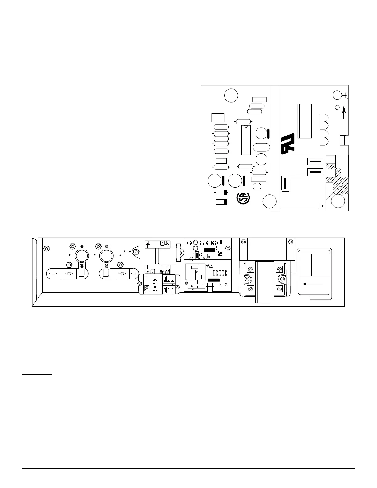
A03010
Fig. 1 – Fan Coil Printed Circuit Board (HK61EA006)
A13032
Fig. 2 – Electric Heater Control Box
FED, FEU, FEM4P, FEM4X, FEV, FXM4, F5M4,
WAHA, WAPM, WAPT, WAPL, WAHM, WAHT,
WAHL, WAXM, WAXT, WAXL, WBGL, WCGL,
WBHL, REM4P, REM4X
Fan Motor
The multi-speed ECM motor used with this product contains two parts:
the control module and the motor winding section. Do not assume the
motor or module is defective if it will not start. Go through the steps
described below before replacing control module or entire motor. The
control module is available as a replacement part.
1. It is normal for the motor to rock back and forth on startup. Do not
replace the motor if this is the only problem identified.
(1.) If the motor is not running:
• Check for proper high voltage and ground at the L,G, and
N connections at the motor. Correct any voltage issue
before proceeding to the next step.
• The motor is communicated through 24VAC signals to
the 1, 2, 3, 4, 5 and C (common) terminals. Not all taps
are programmed, if low voltage is applied to an
non-programmed terminal, the motor will not operate,
which is normal. Verify the part number of the motor
matches the correct replacement motor part number for
the unit model number.
• Initiate a demand from the thermostat and check the
voltage between C (common) and terminal 1- 5. If
voltage is present and the motor isn’t operating, then the
motor/control module is failed.
(2.) Prior to installing the replacement control module, the
motor section condition needs to be verified.
• Check to see if the blower wheel spins freely.
• To check for short to ground, use an ohmmeter to
measure the resistance from any one of the motor
connector pins to the aluminum end plate of the motor.
This resistance should be greater than 100,000 ohms.
®
®
CPC-E
94V-0
LR40061
HSCI
5 AMP
C
T
G
R
SPT
K1
U1
R7
R9
R10
C8
C7
R2
R3
C3
R6
R11
C4
C6
C5
R8
R5
R4
Q1
C1C2
F1
JW1
R1
Z1
D2
D1
NO
NC
FAN
RELAY
C
C
312753
T-O-D 60TX11
HH19ZA945
C9725
L145-55F
312753
T-O-D 60TX11
HH19ZA945
C9725
L145-55F
SPT
FAN
RELAY
NO
NC
5
PULL TO OPEN
WARNING
ELECTRIC SHOCK
HAZARD
DISCONNECT
REMOTE POWER
SUPPLY BEFORE
OPENING PANEL.
322861-101 REV. A
FF1E CONTROL BOX