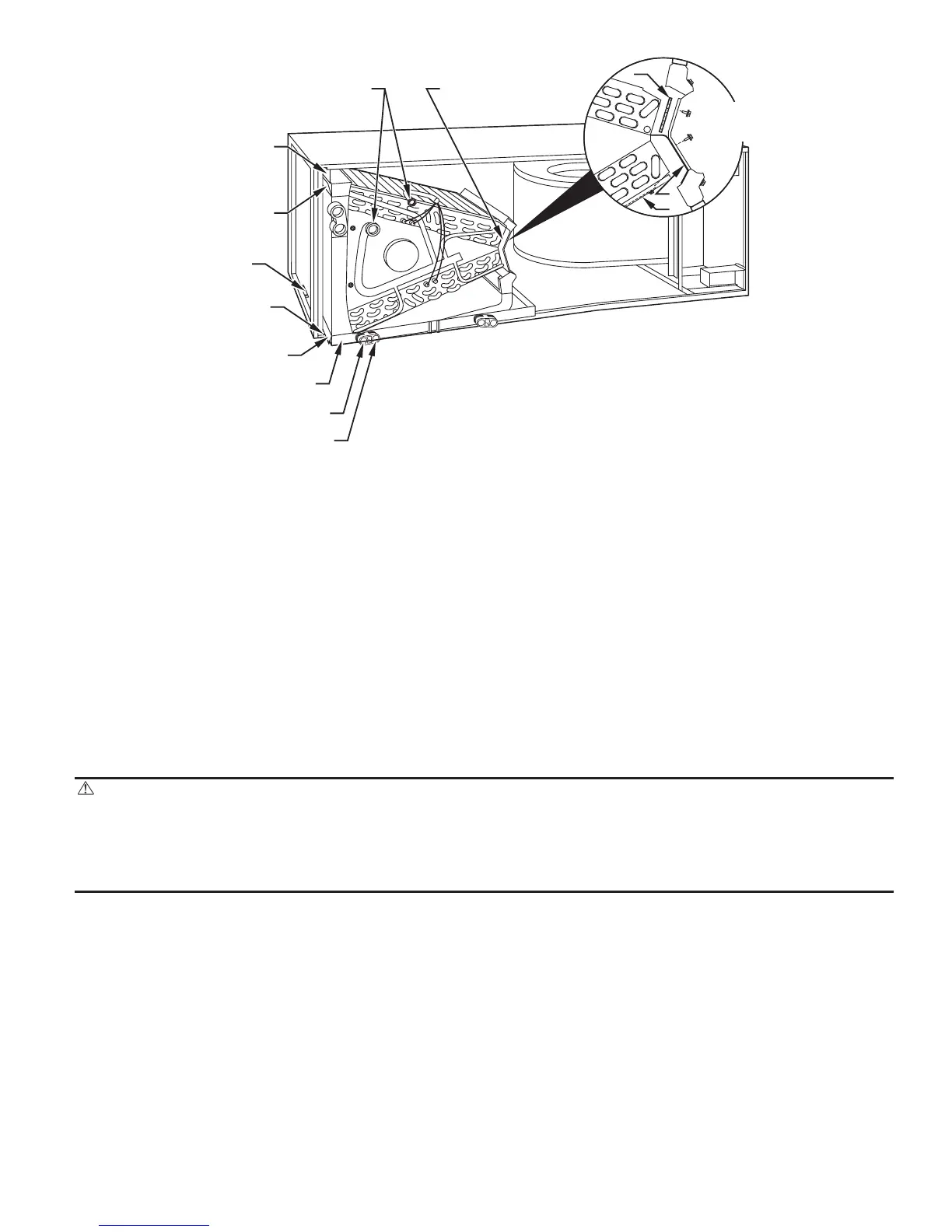
8. Slide coil assembly into casing. Be sure coil bracket on each corner of vertical pan engages coil support rails.
9. Reinstall 2 snap-in clips to correctly position and secure coil assembly in unit. Be sure clip with large offset is used on right side of unit
to secure horizontal pan.
10. Remove two oval fitting caps from left side of the coil, access panel, and fitting panel.
11. Remove insulation knockouts on right side of coil access panel
12. Remove 2 oval coil access panel plugs and reinstall into holes on left side of coil access panel and fitting panel.
13. Install condensate pan fitting caps (from Step 10) in the right side of the coil door making sure that the cap snaps and seats cleanly on the
back side of the coil door. Make sure no insulation interferes with seating of the cap.
14. Reinstall access and fitting panels, aligning holes with tubing connections and condensate pan connections. Be sure to reinstall metal clip
between fitting panel and vertical condensate pan.
Make sure liquid and suction tube grommets are in place to prevent air leaks and cabinet sweating.
F. Downflow Installations
CAUTION: The conversion of the fan coil to downflow requires special procedures for the condensate drains on both
A coil and Slope units. The vertical drains have an overflow hole between the primary and secondary drain holes. This hole
is plugged for all applications except downflow, but must be used for downflow. During the conversion process, remove the
plastic cap covering the vertical drains only and discard. Remove the plug from the overflow hole and discard. At completion
of the downflow installation, caulk around the vertical pan fitting to door joint to retain the low air leak performance of the
unit. Failure to follow this CAUTION could result in personal injury or product and property damage.
In this application, field conversion of the evaporator is required using accessory downflow kit along with an accessory base kit. Use fireproof
resilient gasket, 1/8- to 1/4-in. thick, between duct, unit, and floor.
NOTE: To convert units for downflow applications, refer to Installation Instructions supplied with kit for proper installation. For slope fan coils,
use kit Part No. KFADC0201SLP. For A fan coils use kit Part No. KFADC0401ACL. Use fireproof resilient gasket, 1/8- to 1/4-in. thick, between
duct, unit, and floor.
NOTE: Gasket kit number KFAHD0101SLP is also required for all downflow applications to maintain low air leak/low sweat performance.
G. Manufactured and Mobile Home Housing Applications
1. Fan coil unit must be secured to the structure using field-supplied hardware.
2. Allow a minimum of 24” clearance from access panels.
3. Recommended method of securing for typical applications
a. If fan coil is away from wall, attach pipe strap to top of fan coil using No. 10 self tapping screws. Angle strap down and away from back
of fan coil, remove all slack, and fasten to wall stud of structure using 5/16-in. lag screws. Typical both sides of fan coil.
b. If fan coil is against wall, secure fan coil to wall stud using 1/8-in. thick right-angle brackets. Attach brackets to fan coil using No. 10
self tapping screws and to wall stud using 5/16-in. lag screws. (See Fig. 7.)
Fig. 6—A-Coil in Horizontal-Right Application
A00071
COIL
SUPPORT
RAIL
COIL
BRACKET
DRAIN PAN
SUPPORT
BRACKET
COIL
SUPPORT
RAIL
COIL
BRACKET
HORIZONTAL
DRAIN PAN
PRIMARY DRAIN
HORIZONTAL RIGHT
SECONDARY DRAIN
HORIZONTAL RIGHT
REFRIGERANT
CONNECTIONS
AIR SEAL
ASSEMBLY
A
B
C
HORIZONTAL
RIGHT
APPLICATION
—5—