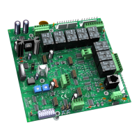
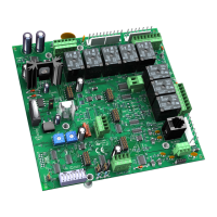
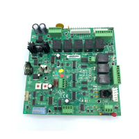
Wiring inputs and outputs
RTU Open v3 Carrier Proprietary and Confidential CARRIER CORPORATION ©2016
Integration Guide All rights reserved
5
- 8
- 7 & 8
Reversing Valve / High
Speed Fan
- 5 & 6
- 2 & 3
- Analog Input
- Analog Output
- Digital Input
- Digital Output
- 24 Vac required at this wire to provide
status. Provide a jumper from
- 1 to
- 9 if
no safeties are used. See "To wire inputs and outputs" in the
RTU Open Installation Guide for additional information on the RTU
Open wiring harness assembly terminations.
Parallel screw terminal at
(
- 1 =
- 6,
- 3 =
- 10,
- 5 =
- 2) may be used in place of the associated flying leads
at the harness (Part# OPN-RTUHRN). See "To wire inputs and outputs" in the
RTU Open Installation Guide for additional
information.
N.C. contact must be used as a primary safety device for approved fire shutdown operation. N.O. contact for monitoring only.
2
If a function other the default is used, do NOT connect wires from J1-x.

 Loading...
