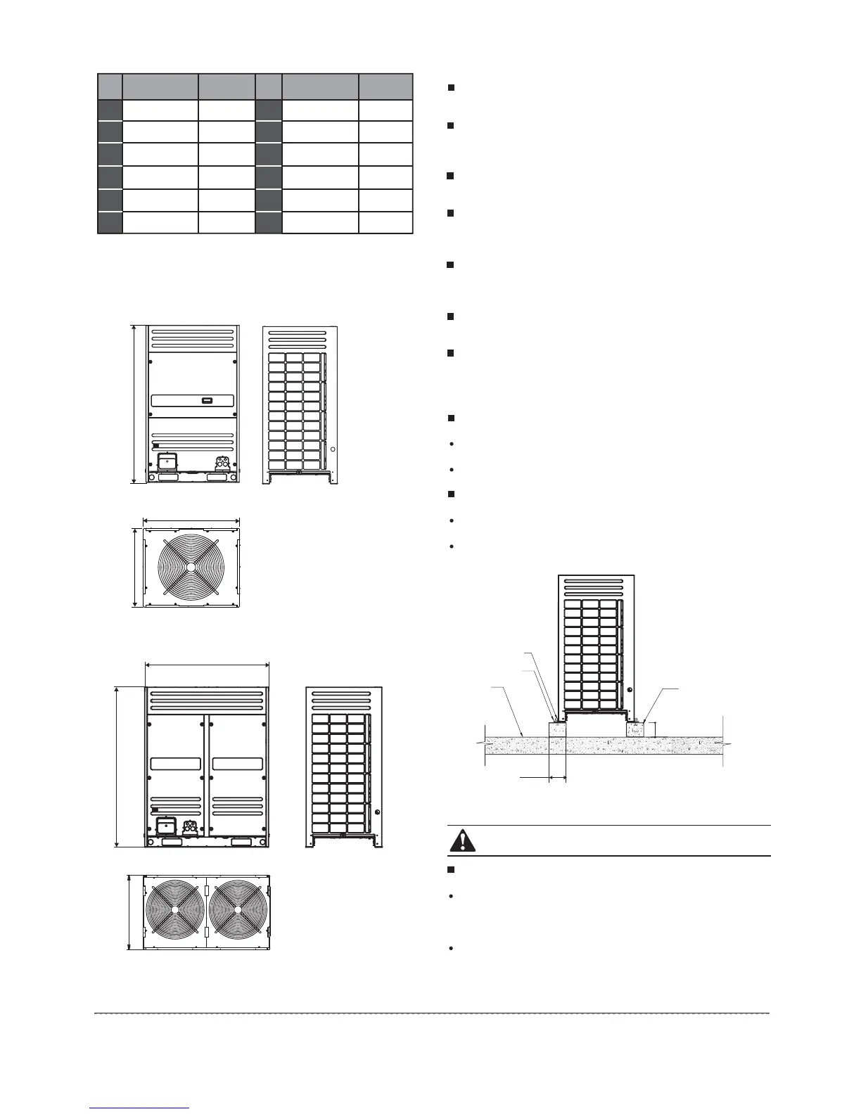
4.2 Dimension of outdoor unit
Fig.4-2
16HP×3
14HP×2+16HP
14HP+16HP×2
64
64
64
44
46
48
Max Qty.of
indoor unit
Mode
HP
Max Qty.of
indoor unit
Mode
HP
Table.4-2
10HP+14HP+16HP×2
14HP×3+16HP
14HP+16HP×3
16HP×4
14HP×2+16HP×2
64
64
64
64
64
56
58
60
62
64
8HP+10HP+16HP×2
10HP+12HP+16HP×2
10HP×2+16HP×2
64
64
64
50
52
54
Fig.4-1
8ǃ10 HP
Unit:mm
12ǃ14ǃ16 ǃ18 HP
Unit:mm
ŐPP
4.3 Selecting installation position
4.4 Base for outdoor unit
Ensure that the outdoor unit is installed in a dry, well-ventilated
place.
Ensure that the noise and exhaust ventilation of the outdoor
unit do not affect the neighbors of the property owner or the
surrounding ventilation.
Ensure that the outdoor unit is installed in a well-ventilated
place that is possibly closest to the indoor unit.
Ensure that the outdoor unit is installed in a cool place without
direct sunshine exposure or direct radiation of high-temp heat
source.
Do not install the outdoor unit in a dirty or severely polluted
place, so as to avoid blockage of the heat exchanger in the
outdoor unit.
Do not install the outdoor unit in a place with oil pollution or full
of harmful gases such as sulfurous gas.
Do not install the outdoor unit in a place surrounded by salty
air. (Except for the models with corrosion-resistant function.)
A solid, correct base can:
Avoid the outdoor unit from sinking.
Avoid the abnormal noise generated due to base.
Base types
Steel structure base
Concrete base (see the figure below for the general making
method)
Fig.4-3
Installation manual
CAUTION
The key points to make basement:
The master unit’s basement must be made on the solid
concrete ground . Refer to the structure diagram to make
concrete basement in detail, or make after field measurements.
In order to ensure every point can contact equality, the
basement should be on completely level.
4
Outdoor unit
Concrete basement
h=200mm
Φ10 Expansion bolt
Rubber shocking
proof mat
Solid ground
or roofing
200mm
 Loading...