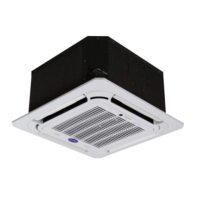
Fig.4-32
Unit: mm
Table.4-9
Fig.4-33
Fig.4-34
Air outlet louver dimension (optional)
B
1290
8000
Remove the two
iron filters firstly
12 ST3.9 self-threading screws
725
3.2
393
765
1250
411 411
213
411 411213
10
Installation manual
NOTE
Before install the air deflector, please ensuring the mesh
enclosure has been took off, otherwise the air supply efficiency
would be block down.
Once mounting the shutter to the unit, air volume, cooling
(heating) capacity and efficiency would be block down, this
affection enhance along with the angle of the shutter. Thus, we
are not recommend you to mount the shutter, if necessary in
use, please adjust the angle of shutter no larger than 15°.
Only one bending site to be allowanced in the air duct (see as
above figure), otherwise, misoperation may led out.
Install the flexible connector between the unit and the air pipe,
for avoiding to produce vibration noise
Example B
Radius
Support
C
1210
A
5.1 Length and drop height permitted of the
refrigerant piping
5. REFRIGERANT PIPE
Table.5-1
Permitted value
Piping
Total pipe length
(Total extended length)
Indoor unit to indoor unit drop height
Pipe length
Drop height
Outdoor unit up
Outdoor unit down
Equivalent length
Actual length
Maximum
piping (L)
Indoor unit-
outdoor unit
drop height
1000m
(Please refer to
the caution 5 of
conditions
2)
175m
200m
(
Please
refer to
caution
1
)
40/90*m
(
Please
refer to
caution
5
)
70m
110m
30m
L1+L2+L3+L4
+L5+L6+L7+L8
+L9h+a+b+c
+d+e+f +g+h+i+j
L1+L5+L8+L9+j
L5+L8+L9+j
(
Please refer to
caution
3
)
Pipe(between the farthest indoor
unit and first branch joint) length
(
Please refer to
caution
4
)
(Pipe diameter
requirements,
please refers
to table. 5-4 or
5-5)

 Loading...
