Fig.4-25
Fig.4-26
Fig.4-27
Fig.4-28
Fig.4-29
Fig.4-30
Fig.4-31
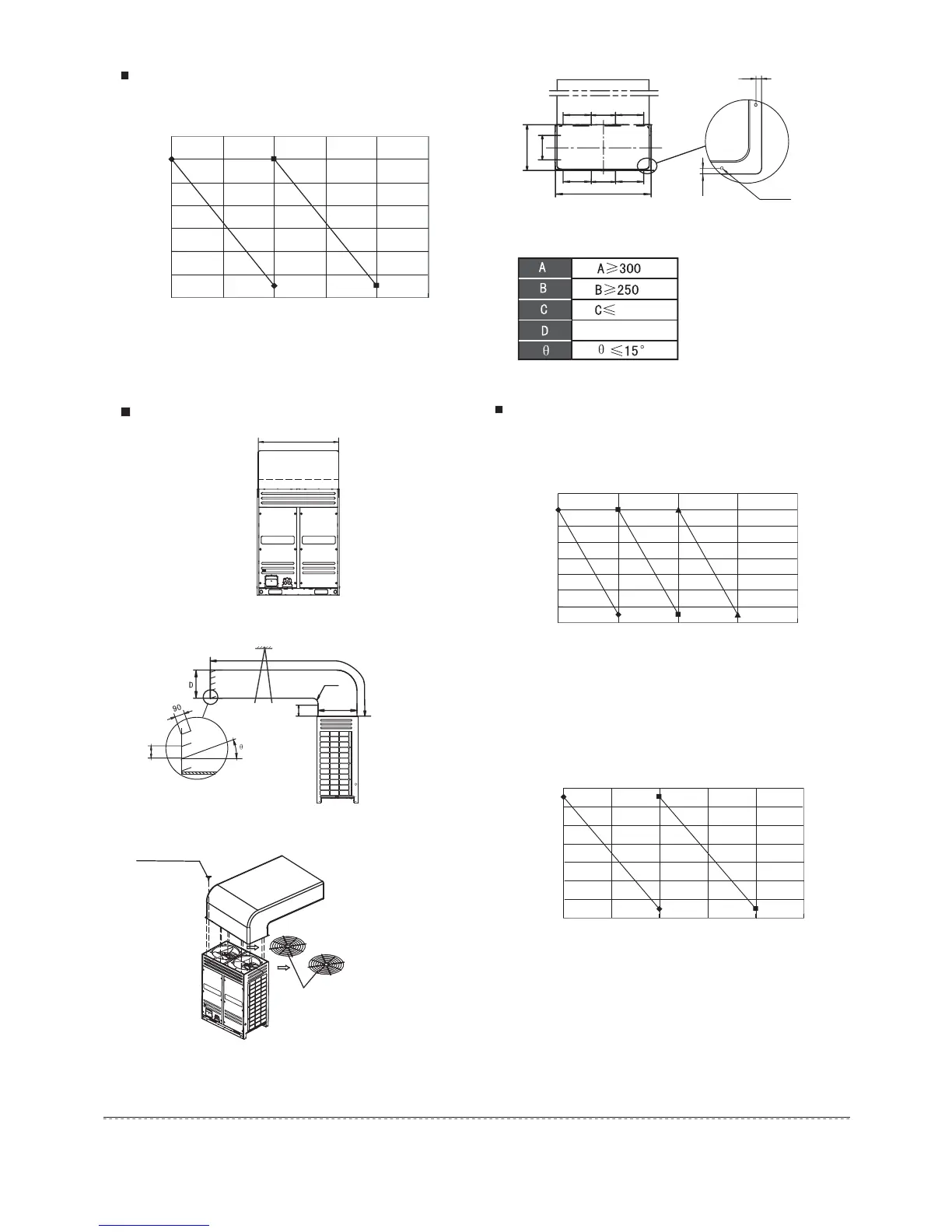
Unit: mmTab le. 4- 8
Air outlet louver dimension (optional)
C
A
725
B
100
10
10
12-Φ3.2
8000
1210
393
765
1250
411 411213
411 411213
9
Installation manual
Example A
12HP, 14HP, 16HP,18HP Installation illustration
Radius
Support
Remove the
two iron filter firstly
12 ST3.9 self-threading screws
Curve diagram of static pressure, air flow volumn.
Curve diagram of static pressure, air flow volumn.
Static pressure (Pa)
Air pressure curve diagram
(take down the mesher)
Air volumeP
K
11400
11600
11800
12000
12200
12400
12600
12800
01020304050
$φ
Default the factory set
%φ
Reserve position,
beed to be customized
Static pressure (Pa)
12600
12800
13000
13200
13400
13600
13800
14000
14200
020406080
Air volumeP
K
$φ
Default
the factory set
%φ
Reserve position,
beed to be customized
&φ
Reserve position,
beed to
be customized
15200
15400
15600
15800
16000
16200
16400
16600
01020304050
Air volumeP
K
$φ
Default
the factory set
%φ
Reserve position,
beed to be customized
Air pressure curve diagram
(take down the mesher)
Air pressure curve diagram
(take down the mesher)
Static pressure (Pa)
12HP
14HPǃ16HPǃ18HP
ŏ'ŏ
 Loading...