Creating a vacuum
Be sure to use the vacuum pump to create a vacuum of the
connective pipe at the air side and liquid side concurrently.
Refrigerant replenishment
If the length is greater than the reference pipe, the refrigerant
replenishment quantity for each system should be calculated
through the formula obtained according to the actual length of
pipe.
Record the refrigerant replenishment quantity, actual length of
pipe and the height difference of the indoor & outdoor unit onto
the operation confirmation table of the outdoor unit in advance
for future reference.
Electric wiring
Select the power supply capacity and wire size according to
the design manual. The power cable of the air conditioner is
generally thicker than the power cable of the motor.
In order to prevent misoperation of the air conditioner, do not
interleave or entwine the power cablewith the connection wires
(low-voltage wires) of the indoor/outdoor unit.
Power on the indoor unit after performing the airtight test and
making a vacuum.
For details of setting the address of the outdoor unit, see
Outdoor unit address bits.
Trial run
Before operation, remove the six pieces of PE foaming which
are used at the rear of the unit for protecting the condenser. Be
careful not to damage the fin. Otherwise, the heat exchange
performance may be affected.
Perform the trial run only after the outdoor unit has been
powered on for over 12 hours.
3
Installation manual
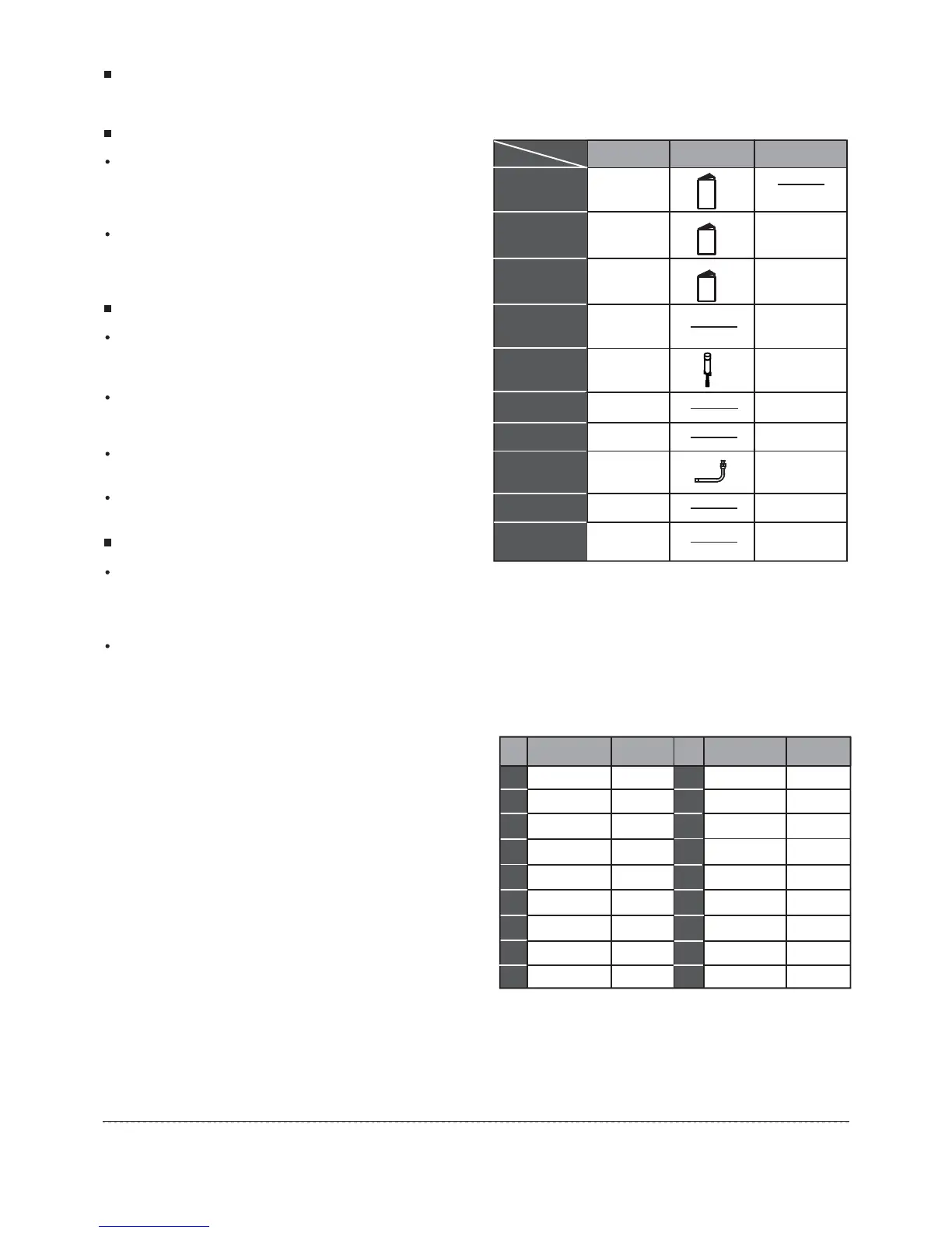
3. ACCESSORIES
4. OUTDOOR UNIT INSTALLATION
4.1 Outdoor unit combination
59
10HP×2+16HP
36
10HP+12HP+16HP
10HP+14HP+16HP
14HP×3
38
63
64
64
40
42
43
46
50
53
56
10HP×2+14HP
10HP+16HP
14HP×2
14HP+16HP
16HP+16HP
26
28
30
32
34
36
39
10HP+12HP
10HP+14HP
22
24
8 8HP×1
13
16
20
23
26
29
33
10HP×1
12HP×1
14HP×1
16HP×1
8HP+10HP
10HP+10HP
10
12
14
16
18
20
Max Qty.of
indoor unit
Mode
HP
Max Qty.of
indoor unit
Mode
HP
Table.4-1
Function
Outdoor unit
installation manual
Outdoor unit
owner’s manual
Indoor unit
owner’s manual
Toggling flathead
screw
Gauge point
subassembly
90° mouthing elbow
Seal plug
Outline
All of units
Model
Name
1
1
1
1
1
1
8
Be sure to deliver
it to the customer
Be sure to deliver
it to the customer
1
Table.3-1
Connective pipe
accessory
Bolt bage
For pipe cleaning
Connect to the side
of liquid pipe
Stone for service
1
Connect to the air
pipe side,use
when it is needed
Switching pipe
(Air side)
1 (the qty. of
12, 14HP are 2)
 Loading...