23
Installation manual
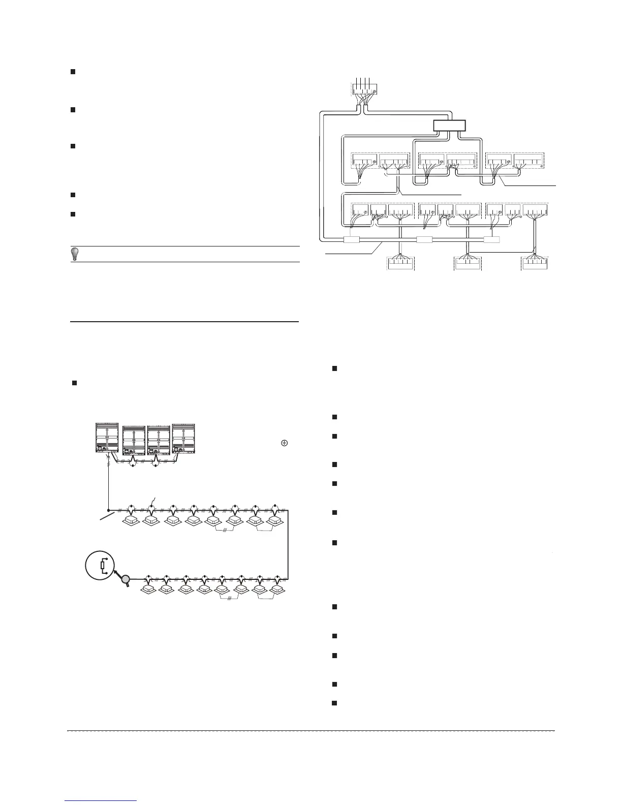
Outdoor unit(master unit)
Outdoor unit(slave unit) Outdoor unit(slave unit)
Signal wire between indoor/outdoor unith
Signal wire between outdoor units
Indoor unit
Indoor unit
Indoor unit
Signal wire between indoor units
Signal wire between indoor unit and wire controller
%&1$ 34((++
/1 (43
%&1$ 34((++ %&1$ 34((++
&'(%$ /1 ( &'(%$ /1 ( &'(%$4343
%&1$
&'(%$ &'(%$ &'(%$
Branch Box
Branch Box
L2
L3
N
L1
Power(380-415V 3N
a
50Hz)
Branch Box Branch Box
Wire controller Wire controller Wire controller
NOTE
The shield net should be grounded at the wiring terminal
of outdoor unit. The inlet and outlet wire net of indoor
communication wire should be connected directly and
could not be grounded, and form open circuit at the shield
net of final indoor unit.
Fig.6-8
Fig.6-9
The control line should be shielded wire. Using other wiring
shall create signal interference, thus leading to error
operation.
The shielded nets at the two sides of shielded wires are
either grounded to the earth, or connected with each other
and jointed to the sheet metal along to the earth.
Control wire could not be bound together with refrigerant
pipeline and power wire. When power wire and control wire
is distributed in parallel form, keep gap between them above
300mm so as to preventing signal interference.
Control wire could not form closed loop.
Control wire has polarity, so be careful when connecting.
Signal wire of indoor/outdoor unit adopts 3-core shielded wire (
≥0.75mm
2
) which has polarity, please connect it correctly.
Check and confirm that refrigeration pipe line and
communication wire with indoor and outdoor unit have
been connected to the same refrigeration system.
Otherwise, operation troubles shall happen.
Power voltage is within ±10% of rated voltage.
Check and confirm that the power wire and control wire
are correctly connected.
Check whether wire controller is properly connected.
Before powering on, confirm there is no short circuit to
each line.
Check whether all units have passed nitrogen
pressure-keeping test for 24 hours with R410A: 40kg/
CM2
.
Confirm whether the system to debugging has been
carried out vacuum drying and packed with refrigeration as
required.
Calculating the additional refrigerant quantity for each set
of unit according to the actual length of liquid pipe.
Keep required refrigerant ready.
Keep system plan, system piping diagram and control
wiring diagram ready.
Record the setting address code on the system plan.
Turn on power switches outdoor unit in advance, and keep
connected for above 12 hours so that heater heating up
refrigerant oil in compressor.
6.7 Signal wire of indoor/outdoor units
6.8 Example for power wire connection
7.1 Inspection and confirmation before
commissioning
7.2 Preparation before debugging
7. TRIAL RUN
6.6 Control system and Installation
(P Q E)
(H1 H2 E) (H1 H2 E) (H1 H2 E)
(H1 H2 E)
34(
Outdoor unit
(master unit)
Outdoor unit
(slave unit)
Outdoor unit
(slave unit)
Outdoor unit
(slave unit)
Signal wire between outdoor units
To closed end of shield wire
(All shield terminals of shield wires
connect to COMM terminal )
Signal wire of
indoor/outdoor units
(open)
group control
The indoor unit at the terminal of communication system should
parallel connect a impedance between port P and port Q.
3
4
matching
resisitor
 Loading...