EasyManua.ls Logo

Carrier SUPRA 850Mt - SECTION 2 DESCRIPTION; System Overview and Models

Carrier SUPRA 850Mt
92 pages
To Next Page IconTo Next Page
To Previous Page IconTo Previous Page
Loading...
2-1
SECTION 2
DESCRIPTION
2.
1
IN
TR
OD
UC
TIO
N
WARNING
Be
wa
re
of
una
nno
unc
ed
st
ar
ti
ng
of
engine or standby motor caused by the
unit thermostat or
the start/st
op
cycle
.
Per
sona
l
Pro
tec
tiv
e
Equi
pme
nt
:
bef
ore
do
in
g
an
yt
hi
ng
on
th
is
pr
od
uc
t,
as
exp
lain
ed
in
this
man
ual.
Alw
ays
use
saf
ety
pre
cau
tion
s
bef
ore
doing
any
maintenance on the unit
s
a
f
e
t
y
g
l
a
s
s
e
s
,
g
l
o
v
e
s
,
sa
fe
ty
sh
oe
s
,
sa
f
et
y
c
lo
t
he
s
a.
Sys
tem
This
man
ual
con
tai
ns
Ope
rati
ng
Data
,
Ele
ctri
cal
Data and Service Instructions for the refrigeration units
listed in Table 2-1. Also Table 2-1 charts some signifi-
cant differences between these models.
The
Supra
Multi-T
emp,
multipl
e
compa
rtment
refrig-
era
tion syste
ms offer
the versa
tili
ty
of
two
or three
compa
rtment
tempera
ture con
trol in
truck.
The Mu
lti-
Temp allows the shipper to ship frozen and perishable
com
mod
itie
s
in
the
sam
e
loa
d
und
er
sep
arat
e
refr
ige
ra-
tion control.
b.
Truc
k condens
ing units
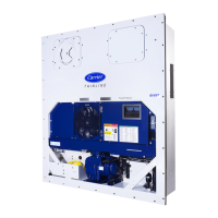
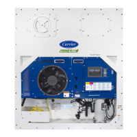
The Supra 750Mt
_
, 850Mt
_
and 950Mt
_
mod
els
are
one piece condensing units designed for truck applica-
tion
s
ava
ila
ble
for
R40
4a
refr
ige
rant
.
They
are
equ
ipp
ed
with an
electric standby motor
.
The model/serial number plate is located inside of
the uni
t
on
the fram
e
as
sh
ow
n
in
Fi
gu
re
2-1 and
Figure 2-2.
fixed on
the frame
fixed on
the micro
The control system is a microprocessor controller
(Re
fer
to
se
cti
on
2.8
).
Onc
e
the
co
ntr
ol
le
r
(
rem
oteCab
Command within the cab of the truck ) is set at the de-
sired temperature, the unit will operate automatically to
maintain the desired temperature within very close lim-
its. The control system automatically selects high and
lo
w
sp
ee
d
co
ol
in
g
or
hi
gh
an
d
lo
w
sp
ee
d
he
ati
ng
as
ne
c-
essary to
mainta
in the
desire
d t
emper
ature.
The
mic
rop
roce
sso
r
con
trol
ler
has
an
autostart/st
op
feature. The auto start/stop operation provides auto-
ma
tic
cyc
li
ng
of
thedie
se
l
en
gi
ne
,
wh
ic
h
inturn
of
fer
s
an
energy efficient alternative to continuous operation of
the
eng
ine
with
con
trol
of
temp
era
ture
by
alte
rnat
e
coo
l-
ing and heating of the supply air (evaporator outlet air).
A
remote
standb
y
recepta
cle
is
standa
rd
with
all
units.
c.
Multite
mpera
ture evapora
tors
The compartments of the Multi-Temp system are
equip
ped with
separa
te evapora
tors.
For Multi-Temp applications, single discharge and
do
ub
le
di
sc
ha
rg
e
ev
ap
ora
tor
s
are
av
ai
la
bl
e.
The
eva
por
ato
rs
are
dif
fere
nt
in
siz
e,
cap
aci
ty
and
num
berof
fa
ns
(
se
e
T
ab
le
2-
2
),
bu
t
al
l
wo
rk
onthe
sa
mepri
nc
ip
le
an
d
us
e
th
e
sa
me
si
ng
le
-p
ha
se
50
Hz
/6
0H
z
fa
n
assembly. The electrical heaters vary according to the
ty
p
e
o
f
c
o
n
d
e
n
s
i
n
g
u
n
i
t
u
s
e
d
a
n
d
n
u
m
b
e
r
o
f
compa
rtments. ( see Figure 2-
3 and
Figure 2-4 )
The evaporator is constructed with plastic profiles
de
si
gn
ed
to
me
et
the
sp
ec
ifi
c
re
qu
ir
em
en
ts
of
the
tran
spo
rt
ind
ustr
y
.
The
air
out
let
pro
file
s
are
des
ign
ed
to
adjust to allow different airspeeds and velocity.
Inside the evaporator housing are one or more of
the following :
240 Volt Single phase backward curved impeller
which supplies high air volumes at low noise levels;
expansion valve; check valve; 12V hot gas solenoid;
12
V
li
qu
id
li
ne
so
le
no
id
;12
V
wa
ter
dra
in
he
ate
r;
electrical heater element; sensor ( defrost termination
sensor ); safety heating thermostat.

Table of Contents

Related product manuals