INSTALLATION,
START UP, AND OPERATING
INSTRUCTIONS
Residential
Non-Programmable
Thermostat
Part Numbers P274-0100-C, P274-0200-C, P274-0300-C
TABLE OF CONTENTS
SAFETY CONSIDERATIONS ...................... 1
INTRODUCTION .................................. 1
INSTALLATION CONSIDERATIONS ............... 1
INSTALLATION ................................. 2-9
Step 1 -- Thermostat Location ................... 2
Step 2 -- Select Model ........................... 2
Step 3 -- Install Thermostat ...................... 2
Step 4 -- Set Thermostat Configuration .......... 3
• TO ENTER CONFIGURATION MODE
• OPTION 01 -- ANTICIPATOR ADJUSTMENT
• OPTION 02 -- CLEAN FILTER TIMER
• OPTION 03 -- FAHRENHEIT/CELSIUS SELECTION
• OPTION 04 --G (FAN) ON WITH W/WI OUTPUT
• OPTION 05 -- HP AND 2S/AC CONFIGURATION
• OPTION 06-- COOLING LOCKOUT
• OPTION 07 -- ZONING ON/OFF CONFIGURATION
• OPTION 08 -- HIGH AMBIENT AUXILIARY HEAT
LOCKOUT
• OPTION 10 -- O (Reversing Valve) ON WITH HEAT
OR COOL SELECTION
• OPTION 13 -- ROOM TEMPERATURE OFFSET
• OPTION 15 -- AUTO MODE ON/OFF SELECTION
• OPTION 18 -- BACKLIGHT CONFIGURATION
• OPTION 19 -- NUMBER OF WIRES
• OPTION 21 -- KEYPAD LOCKOUT
Installer Test Mode ............................... 5
Terminating Installer Test ........................ 5
Step 5 -- Check Thermostat Operation ........... 5
• FAN OPERATION
• OUTDOOR TEMPERATURE SENSOR
• CHECKLIST
OPERATIONAL INFORMATION .................. 10
NON-PROGRAMMABLE THERMOSTAT
CONFIGURATION RECORD ................... I I
NOTE: Read the entire instruction manual before beginning
installation.
SAFETY CONSIDERATIONS
Read and follow manufacturer instructions camlhlly. Fol-
low all local electrical codes during installation. All wiring
must conform to local and national electrical codes. Improper
wiring or installation may dmnage thermostat.
INTRODUCTION
Tot_fline thermostats me wall-mounted, low-voltage ther-
mostats which maintain room temperature by controlling the
operation of a heating and air conditioning system. Separate
heating and cooling set points, plus autochangeover provide
maximum comfort and flexibility. Temperature and mode set-
tings ale preserved with the power off when optional batteries
are used.
INSTALLATION CONSIDERATIONS
Power- All non-programmable thermostats can be dual
powered either by battery operation or electrical operation. AA
batteries are included wifll the product.
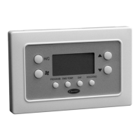
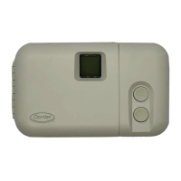
Models -- Ensure the proper thermostat is selected for the
intended application. Refer to Fig. 1 for thermostat dimensions.
Select from the following models:
1. P274-0100-C -- l-stage cool, l-stage heat for air-
conditioning systems only.
2. P274-0200-C -- 1-stage cool, 2-stage heat for a single
speed heat pump, or an air conditioner with 2-stage
heat.
3. P274-0300-C -- 2-stage cool, 2-stage heat for 2-speed
air-conditioning systems, or 2-stage cool, 3-stage heat
for 2-speed heat pump systems.
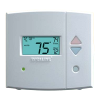
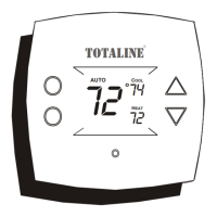
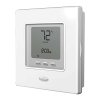
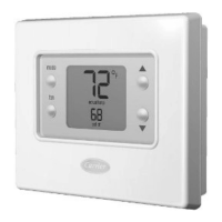
Mode Button
selects be_,oen HEAT
COOL AUTO and OFF operation
Heat pump thetrr c_tat models also m Fan Button
Fndude an EMERGENCY HEATmode¸
up
increase o_ decrease the
desked tempe atur6 setting
LOW BATTERY Indicator _
wJl_ light when batteries
(il In_tal_ed) need t° be replaced
Outdoor Temperature Dlgplay-
Is an optiona_ feature that shows the
outdoor temperature on the LCD
readout
SERVICE FILTER Indicator
lets you know _ _s time to clear_
of replace your systems a# f_lter
Room Temperature Display _
shows cu_ro_t room temperature
COOL ON MdlcMor J
_sd_spl_yed w_on the
cooling equipment is operating /
HEAT ON Indicator
Is d_sp_ayed when the
heating equipment _s
opo_ati0g
AtJXlUARY HEAT Indicator
Fs displayed when a heat pump
system Is operat[ng with auxflla*y
heat a[r filter
P274-0100-C
P274-0200-C
P274-0300-C
HEIGHT (in.) WIDTH (in.) DEPTH (in.)
3V2 53/4 13/8
Fig. 1 -- Totaline Non-Programmable Thermostat
Manufacturer reserves the right to
discontinue, or change at any time,
specifications or designs without notice
and without Incurring obligations.
REPLACEMENT COMPONENTS DIVISION
©CARRIER CORPORATION 2004 9-04
PRINTED IN U.S.A.
LITERATURE NUMBER P274-7SI
REPLACES: 997-510011-19
CATALOG NUMBER 570-351