c. When ducts are used, they must be of the same cross-
sectional area as the free area of the openings to which they
connect. The minimum dimension of rectangular ducts
must not be less than 3 in. (See Fig. 3.)
Do not install the furnace on its back; safety control operation
will be adversely affected. Never connect return-air ducts to
the back of the furnace. A failure to follow this warning can
cause a fire, personal injury, or death.
Step 3—Filter Arrangement
The factory-supplied filter(s) is shipped in the blower compart-
ment. Determine location for the filter and relocate filter retaining
wire if necessary. See Fig. 4 for side return application and Fig. 5
for bottom return application. See Table 3 to determine correct
filter size for desired filter location. Table 3 indicates filter size,
location, and quantity shipped with the furnace.
For bottom air-return applications, filter may need to be cut to fit
some furnace casing widths. A bottom closure panel is factory
installed in the bottom of the furnace. When bottom return inlet is
desired, remove and discard the bottom closure panel. Two sets of
hardware are needed for furnaces in 24-1/2-in. wide casings using
2 filters for bottom return. All hardware is provided for filter
installation.
NOTE: Furnaces with a 17-1/2-in. wide casing require an addi-
tional procedure when locating the filter for bottom return-air
application. Field fabricate a sheet metal filler strip1X3X24-1/2
in. and install it along side of the filter as shown in Fig. 5. Drive
2 screws through the casing side and into the filler strip to secure
it in place. Filter should rest on the top of the filler strip when
installed.
Never operate unit without a filter or with filter access door
removed. Failure to follow this warning can cause fire,
personal injury, or death.
Step 4—Leveling Legs (If Required)
When the furnace is used with side inlet(s) and leveling legs are
required, refer to Fig. 6, and install field-supplied, corrosion-
resistant 5/16-in. machine bolts and nuts.
NOTE: The maximum length of the bolt should not exceed 1-1/2
in.
1. Lay furnace on its back. Locate and drill 5/16-in. diameter
hole in each bottom corner of furnace as shown in Fig. 6.
2. Install nut on bolt and install bolt and nut in hole. (Install flat
washer if desired.)
3. Install another nut on other side of furnace base. (Install flat
washer if desired.)
For Example:
58WAV FURNACE
INPUT BTUH
FREE AREA PER OPENING
(SQ IN.)
ROUND PIPE
(IN. DIA)
44,000 11.0 4
66,000 16.5 5
88,000 22.0 6
110,000 27.5 6
132,000 33.0 7
154,000 38.5 7
For Example:
58WAV FURNACE
INPUT BTUH
FREE AREA PER OPENING
(SQ IN.)
ROUND PIPE
(IN. DIA)
44,000 22.0 6
66,000 33.0 7
88,000 44.0 8
110,000 55.0 9
132,000 66.0 10
154,000 77.0 10
Fig. 3—Air For Combustion and Ventilation
(Outside Air)
A89013
1 SQ IN.
PER
4000
BTUH*
DUCTS
TO
OUTDOORS
1 SQ IN.
PER 4000
BTUH*
SUPPLY
AIR
VENT
THROUGH
ROOF
D
B
A
C
E
1 SQ IN.
PER 4000
BTUH*
DUCT
TO
OUTDOORS
RETURN AIR
1 SQ IN.
PER 2000
BTUH*
1 SQ IN.
PER 2000
BTUH*
DUCTS
TO
OUTDOORS
12″ MAX
12
″ MAX
12″ MAX
Use any of the following
combinations of openings:
A & B C & D D & E F & G
NOTE:
*Minimum dimensions of 3-In.
CONFINED
SPACE
12″
MAX
12″
MAX
OUTDOORS
1 SQ IN.
PER
4000
BTUH*
F
G
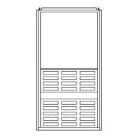
Fig. 4—Side Filter Arrangement
(Control Removed for Clarity)
A93045
FILTER
RETAINER
WASHABLE
FILTER
5

 Loading...