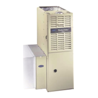
WeatherMaker 8000™
58WAV
Upflow Induced-Combustion Furnaces
Installation, Start-Up, and Operating Instructions
Sizes 045-155, Series 151
NOTE: Read the entire instruction manual before starting the
installation.
This symbol → indicates a change since the last issue.
Index Page
SAFETY CONSIDERATIONS.....................................................1
ELECTROSTATIC DISCHARGE (ESD) PRECAUTIONS
PROCEDURE........................................................................2-3
Dimensional Drawing...............................................................2
Clearances From Combustible Materials.................................3
INTRODUCTION..........................................................................3
LOCATION....................................................................................4
General ......................................................................................4
Location Relative to Cooling Equipment ................................4
Hazardous Locations.................................................................4
AIR FOR COMBUSTION AND VENTILATION...................4-8
Unconfined Space.....................................................................4
Confined Space......................................................................5-6
AIR DUCTS...................................................................................6
General Requirements...............................................................6
Ductwork Acoustical Treatment...............................................6
Supply-Air Connections............................................................6
Return-Air Connections............................................................6
FILTER ARRANGEMENT .......................................................6-7
LEVELING LEGS (IF REQUIRED).........................................7-8
GAS PIPING..................................................................................8
ELECTRICAL CONNECTIONS.............................................8-10
115-v Wiring..........................................................................8-9
24-v Wiring...............................................................................9
Accessories ..........................................................................9-10
VENTING ....................................................................................10
START-UP, ADJUSTMENT, AND SAFETY CHECK ............10
General ....................................................................................10
Sequence Of Operation...........................................................10
Heating Mode..........................................................................12
Cooling Mode .........................................................................12
Continuous Blower Mode.......................................................12
Heat Pump Mode....................................................................12
Start-Up Procedures...........................................................12-13
Adjustments.............................................................................13
Set Gas Input Rate..................................................................13
Set Temperature Rise ........................................................13-17
Set Thermostat Heat Anticipator............................................17
Check Safety Controls............................................................17-18
Checklist.......................................................................................18
SAFETY CONSIDERATIONS
Installing and servicing heating equipment can be hazardous due to
gas and electrical components. Only trained and qualified person-
nel should install, repair, or service heating equipment.
Untrained personnel can perform basic maintenance functions
such as cleaning and replacing air filters. All other operations must
be performed by trained service personnel. When working on
heating equipment, observe precautions in the literature, on tags,
and on labels attached to or shipped with the unit and other safety
precautions that may apply.
Follow all safety codes. In the United States, follow all safety
codes including the National Fuel Gas Code (NFGC) NFPA
54-1999/ANSI Z223.1-1999 and the Installation Standards, Warm
Air Heating and Air Conditioning Systems (NFPA 90B)
ANSI/NFPA 90B.
In Canada, refer to CAN/CGA-B149.1- and .2-M95 National
Standard of Canada, Natural Gas and Propane Installation Codes
(NSCNGPIC).
These instructions cover minimum requirements and conform to
existing national standards and safety codes. In some instances,
these instructions exceed certain local codes and ordinances,
especially those that may not have kept up with changing residen-
tial construction practices. We require these instructions as a
minimum for a safe installation.
Wear safety glasses and work gloves. Have fire extinguisher
available during start-up and adjustment procedures and service
calls.
Recognize safety information. This is the safety-alert symbol
.
When you see this symbol on the furnace and in instructions or
manuals, be alert to the potential for personal injury.
Understand the signal words DANGER, WARNING, CAUTION,
and NOTE. These words are used with the safety-alert symbol.
DANGER identifies the most serious hazards which will result in
severe personal injury or death. WARNING signifies a hazard
which could result in personal injury or death. CAUTION is used
to identify unsafe practices which would result in minor personal
injury or product and property damage. NOTE is used to highlight
suggestions which will result in enhanced installation, reliability,
or operation.
REGISTERED QUALITY SYSTEM
C
a
r
r
i
e
r
C
o
r
p
o
r
a
t
i
o
n
R
E
G
I
S
T
E
R
E
D
F
I
R
M
I
S
O
9
0
0
1
#
A
2
8
8
3
®
EFFICIENCY
RATING
CERTIFIED
CERTIFIED
Visit www.carrier.com
Manufacturer reserves the right to discontinue, or change at any time, specifications or designs without notice and without incurring obligations.
Book 1 4
Tab 6a 8a
PC 101 Catalog No. 535-766 Printed in U.S.A. Form 58WAV-10SI Pg 1 10-00 Replaces: 58WAV-8SI