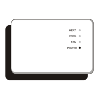
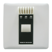
INFRARED RECEIVER
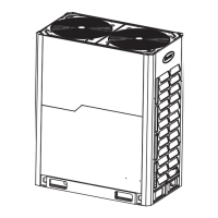
6. Connection
o Thread the connection cable of the panel through the hole in the base.
o Please refer to the installer manual for the wiring connections.
o Remount the panel on the base.
1 Infrared receiver
2 Indoor unit PCB
3 Connection wire (max length 1,8m)
7. Alarms
• The faults of the indoor unit are indicated by the ashing of the light OPER.
• The number of ashes indicates the fault code.
• TIMER indicator light should not be ashing.
• The faults of the outdoor unit are indicated by ashing lights TIMER and OPER.
• The number of ashes of TIMER indicates the tens, OPER indicator light ashes indicates the units, to get
the error code, subtract 20 to the gure obtained.
• The description of the anomaly is indicated in the user or installation manual.
English
3
COMP OPERTIMER
1
2
3
 Loading...