Do you have a question about the Carrier XCT 7 Series and is the answer not in the manual?
Confirms product adherence to European directives for machinery and electromagnetic compatibility.
States product compliance with the EU directive restricting hazardous substances in electrical equipment.
Informs consumers about proper disposal of electrical and electronic products per the WEEE directive.
Explains the symbol indicating the product should not be mixed with household waste and requires specialized disposal.
Details the refrigerant type (R410A) and its Global Warming Potential (GWP) value.
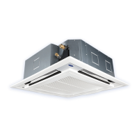
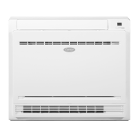
Diagram labeling the upper/lower air outlets, LED panel, IR receiver, and inlet grill of the indoor unit.
Critical warnings for proper installation to prevent water leakage, electric shock, fire, and physical injury.
Important considerations for installation to prevent accidents and ensure structural integrity against hazards.
Precautions for electrical grounding, breaker installation, and handling potential water leakage or airflow issues.
Notes on unit placement, avoiding flammable materials, protecting living things, and user capabilities.
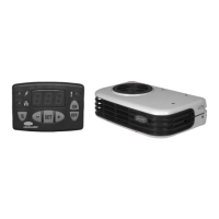
How to use the emergency switch and control indoor airflow direction.
Procedures for test runs and the function that resumes operation after a power outage.
Details various special functions including temperature compensation, defrost, auto start, and room card.
Instructions for cleaning the indoor/outdoor unit, including filter cleaning steps and precautions.
Lists common operational sounds and smells with their potential causes and reasons.
Checklist of items to recheck for common issues like failure to work or bad cooling/heating effects.
Conditions requiring immediate stop of operation and contact with after-service personnel.
Serious warnings and cautions regarding installation risks like injuries, electric shock, and fire.
Criteria for selecting an appropriate installation location for the indoor unit.
Precautions for grounding, drainage, unit placement, and avoiding specific locations to prevent damage or accidents.
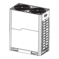
Diagram showing recommended clearances and piping arrangement for indoor unit installation.
Step-by-step guide on removing the front grill of the indoor unit for installation.
Illustrations and instructions for piping connections, including rear, left-rear, and other piping directions.
Methods for fixing the indoor unit body, either on a hanging wall or in a console mode.
Instructions for fixing the wall board and securing the unit on the floor.
Final steps for refrigerant piping, including filling gaps and attaching the front panel.
Detailed instructions for installing the water drainage pipe, including slope requirements and insulation.
Table listing sound power levels and weights for different indoor unit models.
Schematic diagram of the indoor heat exchanger with key components like FAN, EEV, and temperature sensors.
Detailed wiring diagram for the indoor unit, showing PCB connections, sensors, and LEDs.
Table listing error codes, their corresponding flicker times, and error content for indoor unit faults.
Definition and description of DIP switches for setting unit address and capability.
Critical warnings regarding electrical connections, power supply capacity, grounding, and wiring.
Precautions for using copper wires, connecting terminals, power line arrangement, and insulation.
Diagrams showing supply wiring for different indoor unit types and general power connection guidelines.
Diagram illustrating signal wiring connections between outdoor and indoor units for wired controllers.
Describes three methods for connecting wired controllers to indoor units, including polarity and unit roles.
Table detailing specifications for power line and signal line wiring, including cross-section, length, and current ratings.
Specifications for signal wiring of wired controllers, including length and wiring dimensions.
Details on setting indoor unit capabilities and addresses using DIP switches SW01.
Explanation of SW03 switch for automatic or wired controller address setting and centralized controller addresses.
Pre-test run checks including voltage, leakage, piping, and installation review.
Procedures for conducting test runs and performing compulsive cooling/heating if the machine fails to start.
Guidance on identifying and troubleshooting indoor unit faults using fault codes or LED flashing.
Table listing various malfunctions, their flash frequencies, error codes, and notes for troubleshooting.
Advice to contact the dealer for technical support when moving or re-installing the unit.
Information on the restricted substances content in the air conditioner's material composition.
Guidelines for proper refrigerant recycling and scrapping by qualified enterprises.
| Brand | Carrier |
|---|---|
| Model | XCT 7 Series |
| Category | Air Conditioner |
| Language | English |