CARVIN ENGINEERING DATACARVIN ENGINEERING DATA
X1X1
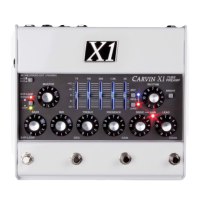
X1 TUBE PREAMP PEDALX1 TUBE PREAMP PEDAL
PG. 5
X1 CONNECTIONS AND CONTROLS CONT.
8. DRIVE CONTROL (Lead channel)
The DRIVE control affects tube harmonics and
saturation of the LEAD channel. The GAIN function (see
#10) increases the effect of the DRIVE. For textured
harmonics with mild tube overdrive, turn the DRIVE
control below “4”. For increased harmonics and sustain,
turn up the DRIVE past “6”. For full blown distortion,
turn on the GAIN footswitch and set the DRIVE control
between “7” and “10”. If feedback occurs at high gain,
move the guitar pickups away from any speakers or
reduce the DRIVE.
9. GAIN LED (Lead channel)
The red LED near the DRIVE control indicates GAIN
mode is ON for the LEAD channel, selected with
the GAIN footswitch (middle-right). The GAIN switch
changes the gain structure of the LEAD channel:
With GAIN OFF, the DRIVE control has the range to
go from a warm clean sound, to a bluesy breakup, to
a dynamic crunch overdrive. GAIN ON increases the
amount of drive available, allowing thick distortion
harmonics while still retaining 12AX7A tube dynamics.
Hi-gain sounds are available without the need for
additional pedals that can limit dynamics.
10. GRAPHIC EQ and RHY & LEAD switches with LEDs
The Graphic Equalizer is a powerful way to shape your
sound. Each fader can be set for up to 12dB of boost
(slide up) or cut (slide down) for each of the 5 frequency
ranges labeled above. To enable the Graphic EQ for
the LEAD or RHYTHM channel, use the small “GEQ”
switches to the right of the faders. ON is indicated by
the small blue LED (RHY channel) or small red LED
(LEAD channel). The Graphic EQ can be set ON or OFF
independently for LEAD or RHYTHM channels and
switched from the (middle-left) “GEQ” footswitch.
The LED lighting in the fader slots will add YELLOW in
the center area when the Graphic EQ is ON.
11. BYP-LOOP SWITCH and LEDs
The small grey “BYP-LOOP” switch changes the
BYPASS function of the LEFT footswitch.
With the small switch OUT, pressing the LEFT
footswitch engages full BYPASS mode. Signal is passed
from the Input jack directly to the outputs unaffected by
any of the controls. In BYPASS the CAB VOICED OUT/
PHONES jack will retain guitar speaker emulation.
In BYPASS mode the signal directly from the INPUT
jack will be amplified at the SPEAKER jack. The red
“BYPASS” LED turns off when full BYPASS is engaged.
With the small switch IN, pressing the LEFT footswitch
bypasses only the (Effects) LOOP. The green “LOOP”
LED is ON when the LOOP is active and shuts OFF
when the LOOP is bypassed.
X1 REAR PANEL CONNECTIONS
12. INPUT
A standard 1/4” INPUT jack feeds the channels, or
bypasses directly to the outputs if BYPASS mode is
engaged. For best results, use a professional quality
guitar cord shorter than 25 feet. Typical cable
capacitance is about 25pF per foot. The longer the
cord, the greater the capacitance, which will reduce the
overall treble response from your guitar pickups.
13. POWER JACK
The POWER jack requires an AC adapter, which is
included with the X1 preamp. Other power sources can
be used, but must have a regulated 12VDC output, 1A
(1000mA) or more and center pin positive (+) polarity.
14. SPEAKER JACK
The SPEAKER jack can drive typical guitar speakers
directly. Multiple speakers can be connected as long as
the total impedance is not below 4 Ohms. For instance,
connecting two 8 ohms speakers in parallel equals a
4 Ohm impedance. In BYPASS mode the signal from
the INPUT jack will be amplified at the SPEAKER jack,
unaffected by any of the X1’s controls. The X1 will not
be harmed by playing without a speaker.
15. LOOP SEND & RETURN JACKS and FOOTSWITCH
Use the SEND jack to connect to an effect’s Input. Use
the RETURN jack to connect to an effect’s Output.
To use the LEFT footswitch to bypass the effects LOOP,
set the small “BYP-LOOP” switch to IN for LOOP bypass
mode. The green “LOOP” LED is ON when the LOOP is
active and OFF if the LOOP is bypassed. Effects will be
heard at the OUTPUT, SPEAKER and CAB VOICED jacks
unless full BYPASS or LOOP BYPASS is engaged (see
#12). Effects like compressor, envelope filter or wah
pedals usually sound best when used between the
guitar and INPUT jack. Effects can also be
used on the OUTPUT or CAB VOICED OUT jacks.
16. OUTPUT
The rear panel OUTPUT jack is for connecting to guitar
amps or power amps which will drive guitar speakers.
The OUTPUT jack can be connected to the front
input of a guitar amp and added or removed from the
signal path using the full BYPASS mode of the LEFT
footswitch similar to using a distortion pedal.
The OUTPUT jack can connect to a power amp input
or to a guitar amp’s “Effects Return” or “Power Amp
In” to drive guitar speakers. Effects can be connected
between the OUTPUT and the amp or used in the
LOOP.
 Loading...