ers, plug in to the rear OUTPUT jack.
If you are listening with amplied full-range
speakers or headphones, plug into the side
PHONES/CAB VOICED OUT jack. A guitar
speaker can be plugged into the SPEAKER
jack.
Plug in the AC apapter to the rear POWER
jack, then plug it into the proper AC voltage.
Allow 30 seconds for the tubes to warm up.
Set the left ON/BYPASS footswitch to light
the red “ON” LED near the MASTER. The
right footswitch selects RHYTHM or LEAD
channels. The middle-right footswitch adds
GAIN for the LEAD channel.
Turn up the MASTER slightly and adjust each
channel VOLUME. Adjust the DRIVE and tone
controls and you’re ready to go.
If you experience problems, rst check
the AC/DC adapter and all connections and
settings. Sometimes the solution is pressing
a switch or turning a dial. If you still feel your
preamp is malfunctioning, contact Carvin.
Tubes can be damaged in shipping.
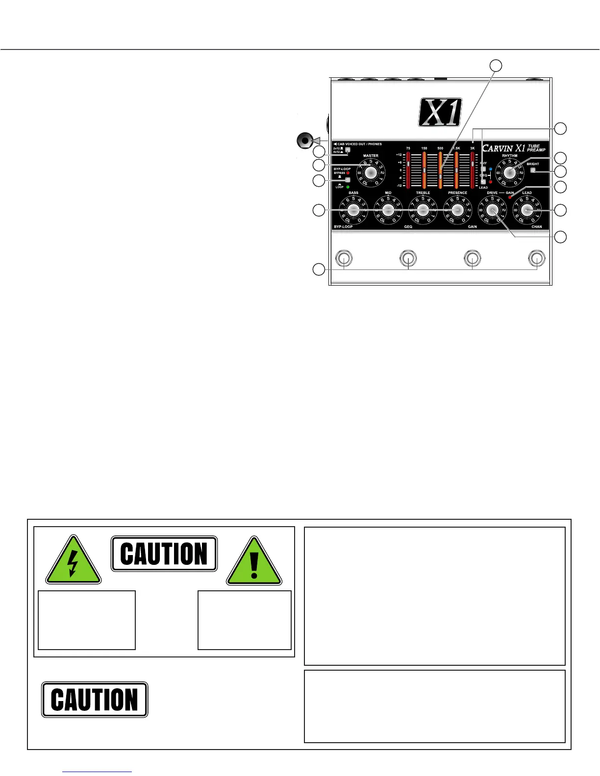
7. LEAD level control
Set the volume of the LEAD channel with this control. The MASTER
control also affects output.
8. DRIVE CONTROL (Lead channel)
The DRIVE control affects tube harmonics and saturation of the LEAD
channel. The GAIN function (see #10) increases the effect of the DRIVE.
For textured harmonics with mild tube overdrive, turn the DRIVE control
below “4”. For increased harmonics and sustain, turn up the DRIVE past
“6”. For full blown distortion, turn on the GAIN footswitch and set the
DRIVE control between “7” and “10”. If feedback occurs at high gain,
move the guitar pickups away from any speakers or reduce the DRIVE.
9. GAIN LED (Lead channel)
The red LED near the DRIVE control indicates GAIN mode is ON for
the LEAD channel, selected with the GAIN footswitch (middle-right).
The GAIN switch changes the gain structure of the LEAD channel:
With GAIN OFF, the DRIVE control has the range to go from a warm
clean sound, to a bluesy breakup, to a dynamic crunch overdrive.
GAIN ON increases the amount of drive available, allowing thick distortion
harmonics while still retaining 12AX7A tube dynamics. Hi-gain sounds are
available without the need for additional pedals that can limit dynamics.
10. GRAPHIC EQ and RHY & LEAD switches with LEDs
The Graphic Equalizer is powerful way to shape your sound. Each fader
can be set for up to 12dB of boost (slide up) or cut (slide down) for each
of the 5 frequency ranges labeled above.
To enable the Graphic EQ for the LEAD or RHYTHM cahnnel, use the
small “GEQ” switches to the right of the faders. ON is indicated by the
small blue LED (RHY channel) or small red LED (LEAD channel).
The Graphic EQ can be set ON or OFF independently for LEAD or
RHYTHM channels and switched from the (middle-left) “GEQ” footswitch.
The LED lighting in the fader slots will add YELLOW in the center area
when the Graphic EQ is ON.
11. BYP-LOOP SWITCH and LEDs
The small grey “BYP-LOOP” switch changes the BYPASS function of
the LEFT footswitch.
With the small switch OUT, pressing the LEFT footswitch engages full
BYPASS mode. Signal is passed from the Input jack directly to the outputs
unaffected by any of the controls. In BYPASS the CAB VOICED OUT/
PHONES jack will retain guitar speaker emulation. In BYPASS mode the
signal directly from the INPUT jack will be amplified at the SPEAKER
jack. The red “BYPASS” LED turns off when full BYPASS is enagaged.
With the small switch IN, pressing the LEFT footswitch bypasses only
the (Effects) LOOP. The green “LOOP” LED is ON when the LOOP is
active and shuts OFF when the LOOP is bypassed.
REAR PANEL
12. INPUT
A standard 1/4” INPUT jack feeds the channels, or bypasses directly
to the outputs if BYPASS mode is engaged. For best results, use a
professional quality guitar cord shorter than 25 feet. Typical cable
capacitance is about 25pF per foot. The longer the cord, the greater the
capacitance, which will reduce the overall treble response from your
guitar pickups.
13. POWER JACK
The POWER jack requires an AC adapter, which is included with the X1
preamp. Other power sources can be used, but must have a regulated
12VDC output, 1A (1000mA) or more and center pin positive (+) polarity.
14. SPEAKER JACK
The SPEAKER jack can drive typical guitar speakers directly. Multiple
speakers can be connected as long as the total impedance is not below 4
Ohms. For instance, connecting two 8 ohms speakers in parallel equals a
4 Ohm impedance. In BYPASS mode the signal from the INPUT jack will
be amplified at the SPEAKER jack, unaffected by any of the X1’s controls.
The X1 will not be harmed by playing without a speaker.
15. LOOP SEND & RETURN JACKS and FOOTSWITCH
Use the SEND jack to connect to an effect’s Input. Use the RETURN
jack to connect to an effect’s Output.
To use the LEFT footswitch to bypass the effects LOOP, set the small
“BYP-LOOP” switch to IN for LOOP bypass mode. The green “LOOP”
LED is ON when the LOOP is active and OFF if the LOOP is bypassed.
Effects will be heard at the OUTPUT, SPEAKER and CAB VOICED jacks
unless full BYPASS or LOOP BYPASS is engaged (see #12).
Effects like compressor, envelope filter or wah pedals usually sound
best when used between the guitar and INPUT jack. Effects can also be
used on the OUTPUT or CAB VOICED OUT jacks.
16. OUTPUT
The rear panel OUTPUT jack is for connecting to guitar amps or power
amps which will drive guitar speakers.
The OUTPUT jack can be connected to the front input of a guitar amp
and added or removed from the signal path using the full BYPASS mode
of the LEFT footswitch similar to using a distortion pedal.
The OUTPUT jack can connect to a power amp input or to a guitar amp’s
“Effects Return” or “Power Amp In” to drive guitar speakers. Effects can
be connected between the OUTPUT and the amp or used in the LOOP.
SIDE PANEL
17. CAB VOICED OUT/PHONES JACK and 2x12/4x12 SWITCH
The side panel CAB VOICED OUT/PHONES jack uses Carvin’s third
generation active cabinet voicing circuit to emulate the response of a
guitar speaker cabinet. This allows you to perform or record tracks without
using guitar speakers. Select a 2x12” or 4x12” cabinet response with the
top panel 2x12-4x12 switch.
The CAB VOICED OUT/PHONES jack will drive recording gear, mixer
inputs, effects or power amps and will drive stereo headphones directly.
Lower the MASTER before plugging in. In BYPASS mode the cabinet
voicing remains active and gets signal directly from the INPUT jack,
unaffected by any controls.
HELP SECTION
A) As with any vacuum tubes in a metal chassis, the X1 chassis will
become warm. If the unit is functioning properly and sounding right this
is typically not a concern.
B) FEEDBACK FROM THE LEAD CHANNEL
The X1 may feedback when the VOLUME, DRIVE, TREBLE and
PRESENCE are turned all the way up. Like other high-gain tube amps,
this is normal. To help control feedback and noise, reduce the DRIVE
or VOLUME, or move the guitar to the side or away from the speakers.
Sometimes replacing a 12AX7A tube can help reduce feedback.
C) TUBE REPLACEMENT GUIDE
It is not uncommon for tubes to malfunction during shipping or after a
long period of time. The tubes may need replacing if the sound becomes
muddy, dull or drops out.
1.) Disconnect the AC adapter from the X1 preamp.
- Do not apply power to the unit with the cover removed!
2.) Remove the chrome nut on the left side for “Phones/Cab Voiced Out”.
3.) Remove the 4 screws on each side, and the 6 bottom screws.
4.) Remove the bottom cover to view the two 12AX7 tubes.
5.) Carefully remove the old tubes with circular motion. *If you can see
cracks in the glass or feel the tube coming apart as you move it, there
may be broken glass. Use a thick towel or thick gloves to remove the tube.
6.) Check the replacement tubes for damage to the glass and carefully
straighten any bent pins if needed.
7.) Carefully insert the new tubes.
8.) Place the bottom cover back on the unit and screw in all screws.
9.) Install the chrome nut and washer on the side jack.
-Done.
1. EQ LIGHTING - COLOR CHANGE
The LED lighting seen through the Graphic EQ’s vertical slots changes
color to indicate the Channel and Graphic EQ selections.
RED indicates the LEAD channel is selected.
BLUE indicates the RHYTHM channel is selected.
When the Graphic EQ is ON the LED lighting inside the slots will add
YELLOW in the center area, ORANGE-YELLOW or BLUE-GREEN.
2. FOOTSWITCHES
The LEFT footswitch is for full BYPASS or effects LOOP switching.
(see #11 for the BYP-LOOP selector switch)
The MIDDLE LEFT footwitch is for Graphic EQ switching (see #10).
The MIDDLE RIGHT footswitch is for GAIN mode on the LEAD channel.
The RIGHT footswitch chooses between the LEAD or RHYTHM channel.
The LED’s inside the Graphic EQ indicate which channel is active.
3. MASTER
Set the MASTER control for overall volume for the OUTPUT, SPEAKER,
and PHONES/CAB VOICED OUT jacks.
4. BASS, MID, TREBLE & PRESENCE (tone controls - both channels)
You can start at 5 on the dial for each of the tone controls. Set these
controls according to the sound you are looking for. Even though you
may have found “your sound”, you may want to change the settings for
different guitars or playing conditions. It’s normal to decrease the BASS
at higher playing levels, or adjust the TREBLE or PRESENCE depending
on the music. Turning up PRESENCE allows you to stand out in the
mix or sound more agressive. Turning PRESENCE down produces a
smoother, thicker sound.
5. RHYTHM level control
This control sets the RHYTHM channel volume. The Rhythm channel
gives you clean, crisp sounds with high headroom. Special mud-cutting
circuits allow clear and vibrant guitar tones to come through. If unwanted
distortion is heard when using high output pickups, lower this control
and raise the MASTER control.
6. BRIGHT SWITCH (Rhythm channel)
The BRIGHT switch increases only the highest guitar harmonics in the
upper fequency range. This is ideal for brightening up dual coil pickups.
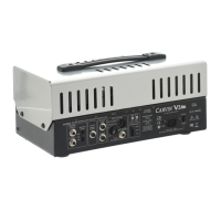
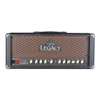
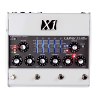
X1 preamp - tOp aND rear paNeLS
REAR PANEL
X1 preamp CONNeCtIONS aND CONtrOLS
12 14 16
17
IMPORTANT! FOR YOUR PROTECTION, PLEASE READ THE FOLLOWING:
WATER AND MOISTURE: Appliance should not be used near water (near a bathtub,
washbowl, kitchen sink, laundry tub, in a wet basement, or near a swimming pool, etc).
Care should be taken so that objects do not fall and liquids are not spilled into the
enclosure through openings.
POWER SOURCES: The appliance should be connected to a power supply only of the
type
described in the operating instructions or as marked on the unit.
GROUNDING OR POLARIZATION: Precautions should be taken so that the grounding or
polarization means of an appliance is not defeated.
POWER CORD PROTECTION: Power supply cords should be routed so that they are
not likely to be walked on or pinched by items placed upon or against them, paying
particular attention to cords at plugs, convenience receptacles, and the point where
they exit from the appliance.
SERVICING: The user should not attempt to service the unit beyond that described in
the operating instructions. All other servicing should be referred to qualified service
personnel.
FUSING: If your unit is equipped with a fuse receptacle, replace only with the same
type fuse. Refer to replacement text on the unit for correct fuse type.
MAINTAINING YOUR EQUIPMENT:
The outer surface of your unit can be wiped with a dry or slightly damp cloth in order
to remove dust and bring back the new look. Avoid spilling liquids or allowing any
other foreign matter inside the unit. As with all pro gear, avoid prolonged use in caustic
environments (salt air). When used in such an environment, be sure the equipment is
adequately protected.
SERVICE:
In the USA, visit our website: www.carvinaudio.com . Outside the USA: contact your
dealer.
RISK OF ELECTRIC SHOCK
DO NOT OPEN
This symbol is intended to
alert the user to the presence
of uninsulated “dangerous
voltage” within the product’s
enclosure that may be of
sufficient magnitude to
constitute a risk of
electric shock to persons.
This symbol is intended to
alert the user to the presence
of important operating and
maintenance (servicing)
instructions in the literature
accompanying the appliance.
RISK OF ELECTRIC SHOCK
DO NOT OPEN
REFER SERVICING TO QUALIFIED
SERVICE PERSONNEL! CAUTION
THIS UNIT CONTAINS HIGH
VOLTAGE INSIDE!
1.) Disconnect the AC adapter from the X1.
- Do not apply power to the unit with the cover
removed! 2.) Remove the chrome nut on the left side
for “Phones/Cab Voiced Out”. 3.) Remove the 4 screws
on each side, and the 6 bottom screws. 4.) Remove the
bottom cover to view the two 12AX7 tubes.
5.) Carefully remove the old tubes with circular motion.
*If you can see cracks in the glass or feel the tube
coming apart as you move it, there may be broken
glass. Use a thick towel or thick gloves to remove the
tube. 6.) Check the replacement tubes for damage
to the glass and carefully straighten any bent pins if
needed. 7.) Carefully insert the new tubes. 8.) Place the
bottom cover back on the unit and screw in all screws.
9.) Install the chrome nut and washer on the side jack.
Done.
SIDE PANEL
17. CAB VOICED OUT/PHONES JACK and 2x12/4x12
SWITCH
The side panel CAB VOICED OUT/PHONES jack uses
Carvin Amplifier’s third generation active cabinet
voicing circuit to emulate the response of a
guitar speaker cabinet. This allows you to perform or
record tracks without using guitar speakers. Select
a 2x12” or 4x12” cabinet response with the top panel
2x12-4x12 switch. The CAB VOICED OUT/PHONES jack
will drive recording gear, mixer inputs, effects or power
amps and will drive stereo headphones directly.
Lower the MASTER before plugging in. In BYPASS
mode the cabinet voicing remains active and gets
signal directly from the INPUT jack, unaffected by any
controls.
 Loading...