Do you have a question about the CAS CI-200 Series and is the answer not in the manual?
Defines 'Warning' for severe risks and 'Attention' for minor risks to safety and property.
Lists various features of the CI-200 series weighing system.
Details the primary functions and capabilities of the weighing indicator.
Technical specifications related to analog input and analog-to-digital conversion.
Information on digital display types, character sizes, and status indicators.
Covers AC adapter, operating temperature, product size, and weight.
Details communication interfaces like RS-232, RS-485 and available options.
Provides dimensional drawings and measurements for CI-200A and CI-201A models.
Provides dimensional drawings and measurements for CI-200S and CI-200SC models.
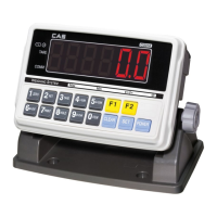
Details the buttons, indicators, and display layout of the CI-200A front panel.
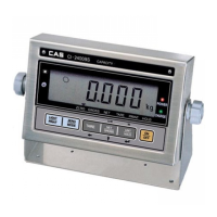
Details the buttons, indicators, and display layout of the CI-201A front panel.
Explains the main weight display and status indicator lamps.
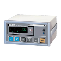
Details the buttons, indicators, and display layout of the CI-200S front panel.
Details the buttons, indicators, and display layout of the CI-200SC front panel.
Explains main display and status indicators for CI-200S/SC.
Identifies and describes the ports and connectors on the rear of CI-200A and CI-201A.
Identifies and describes the ports and connectors on the rear of CI-200S and CI-200SC.
Instructions on connecting the load cell to the indicator, including pin assignments.
Further details on load cell connection, including wiring diagrams and pin functions.
Explains load cell connection diagrams, pin functions, and provides formulas for system design.
Defines weight setup as calibration to match displayed value with actual weight.
Explains the procedure to enter the weight setup mode.
Lists the available calibration functions and their corresponding codes.
Details the function and steps for setting the maximum value in calibration.
Details the function and steps for setting minimum division and decimal position.
Describes setting the multi-calibration step for load cell curve correction.
Explains the procedure for zero calibration.
Details the process of setting the weight for calibration.
Explains the function and steps for weight calibration (span adjustment).
Describes the gravity adjustment function for location-specific calibration.
Details zero adjustment procedures for when zeroing errors occur.
Explains factor calibration, noting its limited use for general users.
Covers setting the dual range function for the indicator.
Step-by-step guide to sealing the indicator after calibration, involving CAL switch bolt and wire.
Instructions on how to access the Set Mode using specific key presses.
Explains the function of keys like ITEM, SET, and CLEAR within the Set Mode.
Details general functions, key assignments, and unit settings.
Covers communication protocols, printer settings, and data initialization.
Describes checker, password, and default initialization functions.
Explains date/time change, power off, A/D speed, and digital filter settings.
Details vibration filter, motion detection, and auto zero tracking compensation.
Covers weight backup, hold types, auto hold range, zero range, and key availability.
Details front key input, function key assignment, and unit selection.
Lists key codes for assigning functions to F1 and F2 keys.
Explains settings for initial zero range and excessive weight check.
Configures backlight behavior on the CI-201A model.
Details settings for backlight and LED brightness levels.
Covers device ID settings and parity bit configuration for serial communication.
Details COM1 baud rate, usage, output format, and output mode settings.
Provides a table of commands for data request signals and output signals.
Lists NT-200 commands, their descriptions, and status for read/write operations.
Details COM2 baud rate, usage, output format, and output mode settings.
Covers printer selection, print format, automatic printing, and line feed settings.
Shows examples of data output for different print formats.
Displays the format for total print, including subtotal and grand total information.
Defines variables and descriptions for CAS DLP protocol data transmission.
Describes the protocol for user-defined output messages via command.
Instructions for entering custom messages using ASCII codes and specific key sequences.
Configures print output, data initialization, and item number printing.
Configures weighing mode for checker or limit functions, with output examples.
Controls the buzzer operation for checker and limit functions.
Details password change and factory default reset.
Explains the procedure for entering the test mode using specific key combinations.
Lists the various diagnostic tests available for the indicator.
Tests the functionality of each key on the indicator, displaying key codes.
Checks the LCD and LED display elements for proper operation.
Verifies load cell connection and A/D converter performance by displaying internal values.
Tests the RS-232 communication port's transmission and reception capabilities.
Confirms printer functionality and connection by printing a test message.
Checks the status of the EEPROM operation, indicating its health.
Displays the current voltage of the indicator's battery.
Monitors the progress of the real-time clock seconds display.
Provides step-by-step instructions on how to access the System Mode.
Displays initial screens for Weighing, Counting, and Percent Modes.
Guides users on how to input samples for Piece Counting System (PCS) mode.
Explains direct input methods for sample weight and count in PCS mode.
Guides users on how to input samples for percentage calculation in Percent Mode.
Explains direct input methods for sample weight and percentage in Percent Mode.
Describes how to input or register an item number (ID) for weighing items.
Explains how to use the tare function with specific keys.
Details how to display and print subtotal, total, and weighing count.
Instructions for setting the high limit value for weighing operations.
Instructions for setting the low limit value for weighing operations.
Explains zeroing with LED indicators, considering zero point range.
Describes tare function with LED indicators, including saving tare and checking weights.
Details ordinary and automatic hold functions using LED indicators for moving objects.
Explains zeroing with LCD display, considering zero point range.
Describes tare function with LCD display, including saving tare and checking weights.
Details ordinary and automatic hold functions using LCD display for moving objects.
Instructions on charging the internal battery, including indicator lights and charging time.
Provides estimated battery usage times for different models and backlight settings.
Shows pin diagrams for connecting COM1 and COM2 ports to computers or other devices.
Guides on connecting auxiliary displays and label printers via serial communication.
Introduces the RS-232 communication protocols used by the indicator.
Details data format, code, and transmission settings for 22-byte CAS communication.
Outlines data format, code, and transmission settings for 10-byte CAS communication.
Describes data format, code, and transmission settings for 18-byte AND communication.
Explains RS-422/485 communication, connection diagrams, and usage.
Lists errors encountered during weight setup and their corresponding solutions.
Lists common errors during weighing operations and their resolution steps.
Explains abbreviations commonly shown on the indicator's display.
Provides a reference table for ASCII character codes and their corresponding values.
| Brand | CAS |
|---|---|
| Model | CI-200 Series |
| Category | Accessories |
| Language | English |