J
Jordan MerrittAug 19, 2025
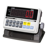
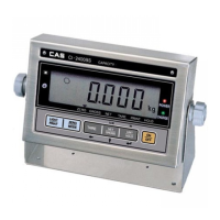
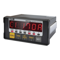
How to fix 'current weight deviates from zero range' error on CAS CI-2001A Accessories?
- BBrett ThomasAug 19, 2025
If your CAS Accessories scale shows that the current weight deviates from the zero range, you can press the ZERO key. Note that this only works if the deviation is within 10% of the maximum capacity.