17
INSTALLATION
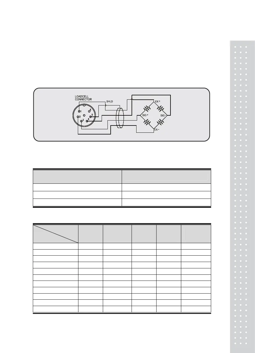
■ LoadCell Connection
Connect load cell connector to load cell port which is in the
backside of indicator.
► Connection Method
Ref. Each L/C manufacturer's or model's wire color could be
different. In that case, please note the following diagram.
► Resolution to loadcell output rate
Loadcell Sense Voltage
for 5V Excitation Voltage
Recommended resolution
2 mV 1/1,000 (Max)
4 mV 1/2,000 (Max)
10 mV 1/5,000 (Max)
►
Manufacturer's wire colors
Connector
Corperation
No.1
(EX+)
No.2
(EX-)
No.3
(SIG+)
No.4
(SIG-)
No.5
(Shield)
CAS RED WHITE GREEN BLUE SHIELD
KYOWA RED BLACK GREEN WHITE SHIELD
INTERFACE RED BLACK GREEN WHITE SHIELD
P.T RED BLACK GREEN WHITE SHIELD
BLS GREEN BLACK WHITE RED YELLOW
SHOWA RED BLUE WHITE BLACK SHIELD
SHINKOH RED BLACK GREEN WHITE SHIELD
TMI RED WHITE GREEN BLUE YELLOW
TML RED BLACK WHITE GREEN SHIELD
TFAC RED BLUE WHITE BLACK YELLOW
HUNTLEIGH GREEN BLACK RED WHITE SHIELD