The CAS CI-2001AS/BS is an industrial weighing indicator designed for various industrial applications, offering robust performance and user-friendly features.
Function Description:
The CI-2001AS/BS indicator is a core component of a weighing system, converting load cell signals into digital weight readings. It supports both gross and net weight display, tare functions, and zero calibration. The device is equipped with a watchdog circuitry for system restoration and offers full digital calibration, specifically a Single Pass Automatic Span Calibration (SPAC™) for simplified setup. It can be wall-mounted and is designed for easy operation with various functions.
Important Technical Specifications:
Analog Part:
- Load cell excitation voltage: DC 5V, capable of connecting up to 4 x 350Ω load cells.
- Full scale input signal: 20mV, including dead load.
- Zero adjust range: 0.05mV ~ 5mV.
- Input sensitivity: 2µV/D (H-44, OIML) and 0.5µV/D (Non H-44, OIML).
- System linearity: Within 0.01% of FS.
- A/D internal resolution: Approximately 200,000 counts.
- A/D external resolution: 5,000dd (H-44, OIML) and 30,000dd (Non H-44, OIML).
- A/D conversion speed: 10 times/sec.
Digital Part:
- Span calibration: Full Digital Calibration: SPAC™ (Single pass automatic span calibration).
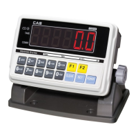
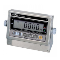
- Display: CI-2001AS features a 6-digit LED display, while CI-2001BS has a 5-digit LCD display.
- Size of letter: 25mm (Height) for both models.
- Display below zero: Shows a "-" minus signal.
- Additional symbols: CI-2001AS displays Zero, Tare, Gross, Net, Stable. CI-2001BS displays Zero, Net, Stable.
- AC adapter: AC 110V/220V, 50/60Hz (DC 12V, 500mA).
- Power consumption: CI-2001AS: 10W, CI-2001BS: 1W.
- Operating temperature: -10℃ ~ +40℃.
- Overall dimensions: 200mm x 130mm x 53mm.
- Weight: 2kg.
Optional Features:
- Serial Interface: RS-422/485.
- Inner Clock.
- Built-in Battery.
Usage Features:
Front Panel (CI-2001AS):
- Display Lamps:
- STABLE: ON when weight is stable.
- GROSS: ON when current weight is gross.
- NET: ON when current weight is net.
- TARE: ON when tare weight is stored.
- ZERO: ON when current weight is 0kg (0lb).
- Keyboard:
- ▲ (Up/Increase): Increases set value, increases first place value to 1.
- ◄ (Left/Shift): Changes the digit of the set value, moves to the left by 1 place. Used for numeral input in TEST, CAL, SET modes.
- ZERO: Returns display to 0.
- TARE: Used for container weighing, memorizes current weight as tare. Releases tare setting if pressed in unload condition.
- GROSS/NET: Toggles between gross and net weight display.
- PRINT: (CI-2001AS kg only version) Prints current weight. Pressing for more than 3 seconds activates total print.
- kg/lb: (CI-2001AS kg/lb conversion version) Toggles between lb and kg units.
- ENTER: (CI-2001AS kg only version) Functions as PRINT key for total print (long press). In CALIBRATION, TEST, SET modes, stores current condition and exits.
Front Panel (CI-2001BS):
- Display Lamps:
- kg: ON when unit is kilogram.
- lb: ON when unit is pound.
- STABLE: ON when weight is stable.
- NET: ON when current weight is net.
- ZERO: ON when current weight is 0kg (0lb).
- Keyboard: Similar to CI-2001AS with ▲, ◄, ZERO, TARE.
- GROSS/NET: Toggles between gross and net weight display.
- PRINT: (CI-2001BS kg only version) Prints current weight. Long press for total print.
- kg/lb: (CI-2001BS kg/lb conversion version) Toggles between lb and kg units.
- ENTER: (CI-2001BS kg only version) Functions as PRINT key for total print (long press). In CALIBRATION, TEST, SET modes, stores current condition and exits. Also functions as LCD manual backlight key.
Connecting the Cable:
- DC ADAPTER (0V, +12V): Port for DC power.
- RS-485 Interface: For serial interface (computer, etc.).
- RS-232 Interface: For serial interface (computer, printer, remote display).
- LOAD CELL: For connecting load cell (Ex+, Ex-, Sig+, Sig-, GND).
- Legal Seal: Instructions provided for installing the seal on the wire loop.
Operating Modes:
- TEST Mode: Accessed by pressing "On/Off" key while holding "PRINT" (CI-2001AS kg only) or "kg/lb" (CI-2001AS/BS kg/lb). Includes Key test, LED/LCD display test, Load cell test and A/D conversion test, Serial interface test (RS-232), and Printer test.
- CALIBRATION Mode: Accessed by pressing "On/Off" key while holding the CAL switch on the rear panel. Includes Maximum capacity setting, Minimum division setting, Setting weight for span calibration, Zero calibration, and Span calibration.
- SET Mode: Accessed by pressing "On/Off" key while holding "ENTER" key. Allows setting various parameters like primary base unit (kg/lb), serial port usage, automatic zero tracking compensation, digital filter, weight back-up mode, "ENTER" key usage, device ID, serial interface baud rate, serial interface output mode, HOLD type, and clock option.
Serial Interface (RS-232C and RS-422/485):
- Transmit Data Format: 22 bytes, including US/ST/GS/NT/OL status, Device ID, 8 bytes of data (weight with decimal point), CR, and LF.
- Device ID: 1-byte ID for selective data reception.
- Simple Interface Program: BASIC language example provided for communication.
- RS-232C Connection: Detailed pinouts for 25-pin (Female) and 9-pin (Female) serial ports, and 9-pin (Male) for sub-display connection.
- RS-422/485 Connection: Detailed pinouts for RS-485 port connection to a serial port device and a remote sub-display.
Maintenance Features (Error Messages & Troubleshooting):
The manual provides a comprehensive list of error messages and corresponding troubleshooting steps for both Weighing Mode and Calibration Mode.
Errors in Weighing Mode:
- Err 02 (Load cell connection failure/A/D conversion error): Check load cell connector and signal polarity.
- Err 06 (Printer connection error): Check printer connector; if issue persists, contact service.
- Err 08 (ZERO/TARE key operation in unstable condition): Press ZERO or TARE key in stable condition.
- Err 10 (Tare weight exceeds maximum capacity): Set tare to be smaller than maximum capacity or reset calibration.
- Err 13 (Zero range deviates from set range): Confirm platform is empty; if so, perform calibration.
- Over (Weight on platform too heavy): Do not exceed maximum tolerance; if load cell is damaged, replace it.
Errors in Calibration Mode:
- Err 21 (Resolution exceeds limit 1/50,000): Lower the resolution by modifying allowed weight (CAL 1) or division (CAL 2).
- Err 22 (Span calibration weight too low): Set span calibration weight in CAL 3 to be more than 10% of maximum capacity.
- Err 23 (Span calibration weight too high): Set span calibration weight within maximum capacity (CAL 1).
- Err 24 (Load cell output too small at SPAN calibration): Proceed calibration with less resolution. Recommended resolutions provided for different load cell sense voltages (2mV: 1/1,000; 4mV: 1/2,000; 10mV: 1/5,000).
- Err 25 (Load cell output too large at SPAN calibration): Proceed calibration with less resolution.
- Err 26 (Load cell output too large at ZERO calibration): Check if platform is empty; proceed calibration after checking in A/D TEST mode.
The manual concludes with a notice that specifications are subject to change for improvement without notice.