Do you have a question about the CAS CI-6000A Series and is the answer not in the manual?
Important safety guidelines for operating the weighing indicator.
Highlights of the weighing indicator, including speed, accuracy, data saving, and control capabilities.
Technical details of the analog input and A/D conversion.
Specifications for digital parts like calibration, input noise, and display.
Physical dimensions, weight, and operating temperature range.
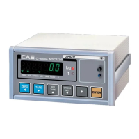
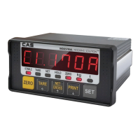
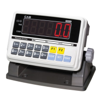
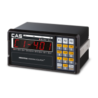
Visual representation of the indicator with physical dimensions.
Explanation of the VFD display and status indicator lamps.
Detailed functions of each key on the front panel keyboard.
Diagram showing all ports on the rear panel.
Specifications for RS-232/RS-485 interfaces and their functions.
Details on load cell connection, external I/O, and option ports.
Instructions for connecting load cells and setting up power supply.
Steps to access, navigate, and use keys in calibration mode.
Overview and detailed steps for calibration functions.
Explanations and solutions for common calibration errors.
Instructions for sealing calibration switches and connectors.
Steps to enter and use the set mode menu.
Comprehensive list of configurable parameters and their functions.
How to select and perform various tests on indicator functions.
How to start weighing mode and use front panel keys.
Various methods to input set-point values and codes.
Logic for output control and mode selection in batching.
Configuration of COM ports, baud rates, and data transmission formats.
Pin assignments and wiring diagrams for serial interfaces.
Specifications and setup for analog current/voltage and BCD outputs.
Guide to configuring analog output type and range using switches.
Explains error messages for stability, connection, keys, and calibration.
Explains errors related to tare weight, zero range, and capacity limits.
Explains errors specific to batching modes, like weight limits.
| Brand | CAS |
|---|---|
| Model | CI-6000A Series |
| Category | Accessories |
| Language | English |