Do you have a question about the CAS CI-170A and is the answer not in the manual?
Covers safe setup, cleaning, key operation, and environmental protection.
Addresses avoiding sudden temperature changes and EMI noise.
Highlights high quality, accuracy, display, operation, and main functions.
Details voltage, sensitivity, resolution, and speed for analog conversion.
Covers span calibration, input noise, display, capacity, and division.
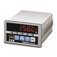
Explains the meaning of status lamps like STABLE, TARE, NET, HOLD, ZERO, KG, TON.
Lists power, size, temperature, weight, power consumption, and optional parts.
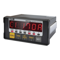
Describes the function of each indicator lamp on the front panel.
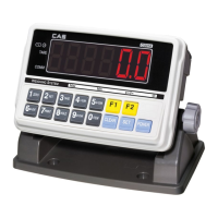
Explains the purpose of each key (ZERO, TARE, NET/GROSS, PRINT, SET).
Details the pin assignments and connection method for load cells.
Provides a table showing wire colors for different load cell manufacturers.
Shows how numbers 0-9 are displayed on the 7-segment display.
Shows how letters A-Z are displayed on the 7-segment display.
Explains how to enter test mode and use keys for navigation.
Lists all available tests from TEST 1 to TEST 8.
Verifies the functionality of each key on the indicator.
Checks the indicator's display output.
Tests the load cell and A/D conversion function.
Tests RS-232 and RS-485 communication with a computer.
Verifies the printer connection and functionality.
Tests the analog output function (option).
Tests external input and output functions (option).
Tests the Real-Time Clock function (option).
Instructs how to access the calibration functions using specific keys.
Lists all available calibration menus from CAL 1 to CAL 9.
Sets the maximum weighing capacity and units (kg, ton).
Configures the minimum division and decimal point for the scale.
Guides through zero calibration and span calibration steps.
Allows direct input of zero and span values for load cell calibration.
Adjusts zero calibration when errors occur or due to load cell shock.
Allows calibration using a factor, typically for multi-calibration setups.
Adjusts the scale based on gravity at the production or usage location.
Configures the scale to operate with two different weighing ranges.
Explains how to enter Set Mode and the functions of its keys.
Configures AD speed, filters, key lock, operating conditions, etc.
Configures RS232, RS485 ports, baud rates, and output formats.
Manages print usage, forms, line feed, and print conditions.
Allows setting the date and time for the Real-Time Clock.
Configures analog output range, voltage, current, and dual output.
Sets up relay modes, external inputs, and delay times for output control.
Explains how to activate the weighing mode via the power switch.
Details the functions of ZERO, TARE, NET/GROSS, PRINT, and SET keys during weighing.
Provides step-by-step examples for common operations like zero compensation and tare.
Shows the pin configuration for the RS232 serial port connection.
Illustrates the pin layout for RS485 serial communication (optional).
Diagrams the wiring for external input and output terminals.
Details the byte structure for CAS and AND data transmission.
Explains commands for reading and writing data in Command Mode 1.
Describes command mode 3 and provides an ASCII table.
Explains the Modbus-RTU protocol, data format, and supported functions.
Guides on using the MIGUN protocol, including commands and data transmission.
Lists commands to request specific data from the indicator.
Lists commands to set or change indicator parameters.
Describes CRC checks, timeouts, and specific error codes for communication issues.
Lists Modbus registers, their descriptions, input values, and access modes.
Details errors occurring during calibration and provides solutions.
Lists errors encountered during weighing operations and their remedies.
| Brand | CAS |
|---|---|
| Model | CI-170A |
| Category | Accessories |
| Language | English |