6871082-R2 17
ADJUSTING PAD CAMBER
FLEXIBLE (ADJUSTA-BLOCK) DESIGN
CL5054.eps
3
4
1
2
C
B
A
C
B
A
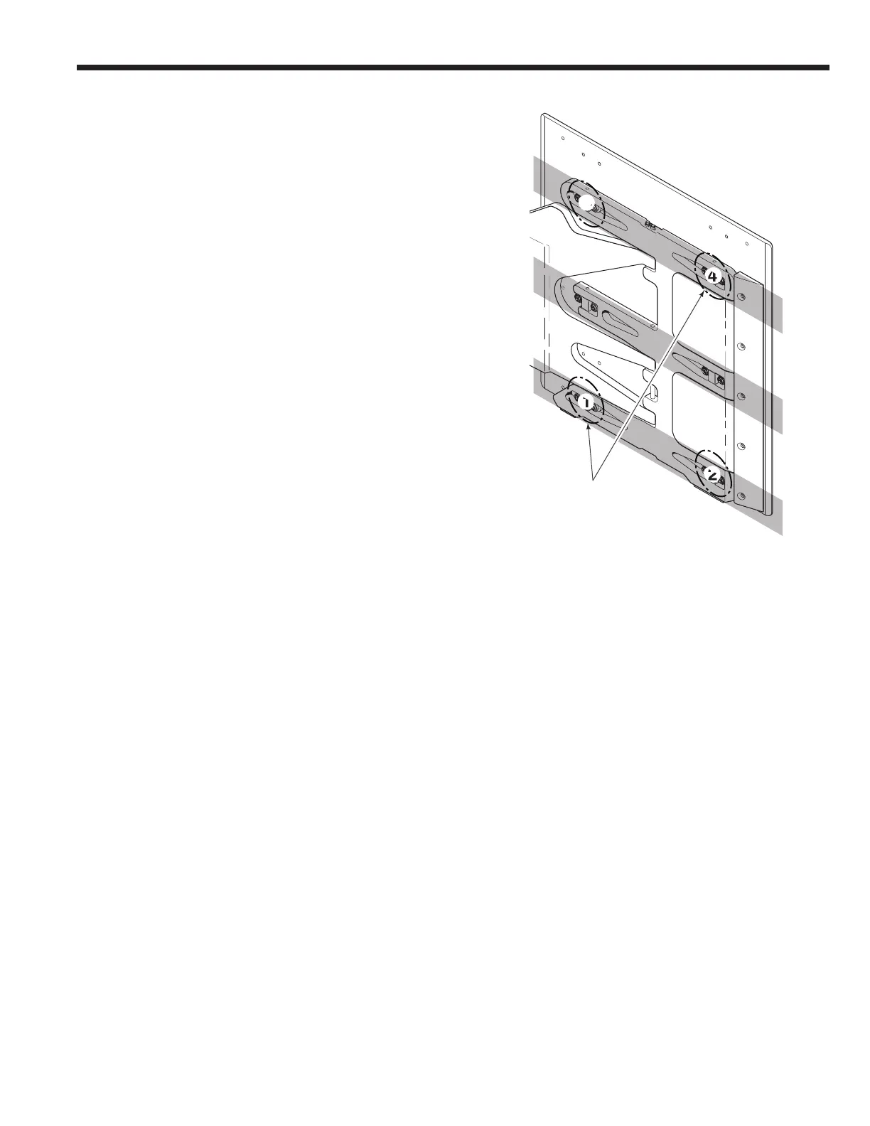
7 Adjustment Sequence –
• Adjust force at location 2 to the desired specification.
Validate clamp force with tester and adjust as
required.
• Adjust force at location 4 to the desired specification.
Validate clamp force with tester and adjust as
required.
• Adjust force at location 1 to the desired specification.
Validate clamp force with tester and adjust as
required.
• Adjust force at location 3 to the desired specification.
Validate clamp force with tester and adjust as
required.
IMPORTANT: When adjustments are made in Rows
A or C, Row B must be adjusted by 1/2.
Example 1: If location 2 in row C is increased by
0.08 in. (2 mm), the location above 2 in row B must
be increased by 0.04 in. (1 mm).
Example 2: If location 3 in row A is decreased by
0.08 in. (2 mm), the location below 3 in row B must
be decreased by 0.04 in. (1 mm).
Rows
Locations
RH Pad