SECTION 58 - DRIVELINES - CHAPTER 2
58-13
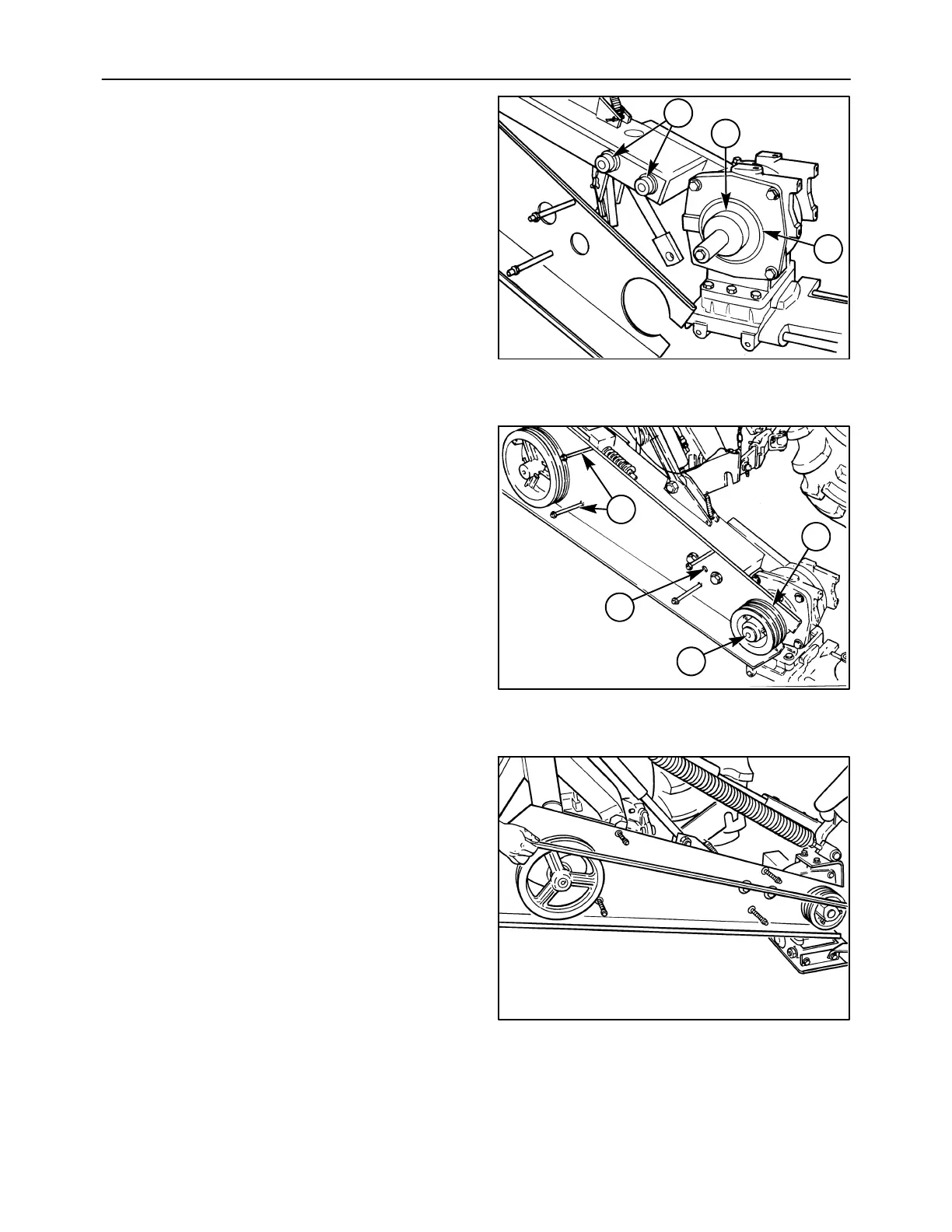
4. Apply grease to the remaining “T-seal” washer,
and install it on the bevel gearbox rear pivot hub,
1, so that it fits into the groove, 2. Install the rear
pivot arm by sliding it over the input shaft onto the
gearbox pivot hub, and at the same time fitting it
over the two mounting bosses, 3, on the lift arm.
Install the 3/4 inch Grade 8 cap screws and torque
to 560 N⋅m (413 lb ft) to retain the pivot arm.
5. Slide the inner shield over the bevel gearbox input
shaft, and secure it by installing the left side studs,
1, and jam nuts, and the 3/8 inch cap screw, 2, and
washer.
6. Install the key into the keyway on the bevel
gearbox input shaft, and slide the sheave, 3, onto
the input shaft over the key.
7. Use a long straightedge to align the sheave to the
drive sheave; the two sheaves should be aligned
within 1/16 inch. Tighten the two set screws
securely, and tighten the jam nuts. After the
sheave is tightened to the shaft, install the cap
screw, 4, Figure 27, and washer in the end of the
shaft. Block the cutter bar, and tighten the cap
screw.
600-4-6
1
2
3
26
600-4-4
1
2
3
4
27
A3679-27
28