SECTION 58 - DRIVELINES - CHAPTER 2
58-14
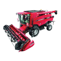
8. Reinstall the belt onto the sheaves, and tighten
the spring adjuster nut, 2, until the spring length,
1, matches the length of the gauge. Reinstall the
outer belt shield using four locknuts and flat
washers.
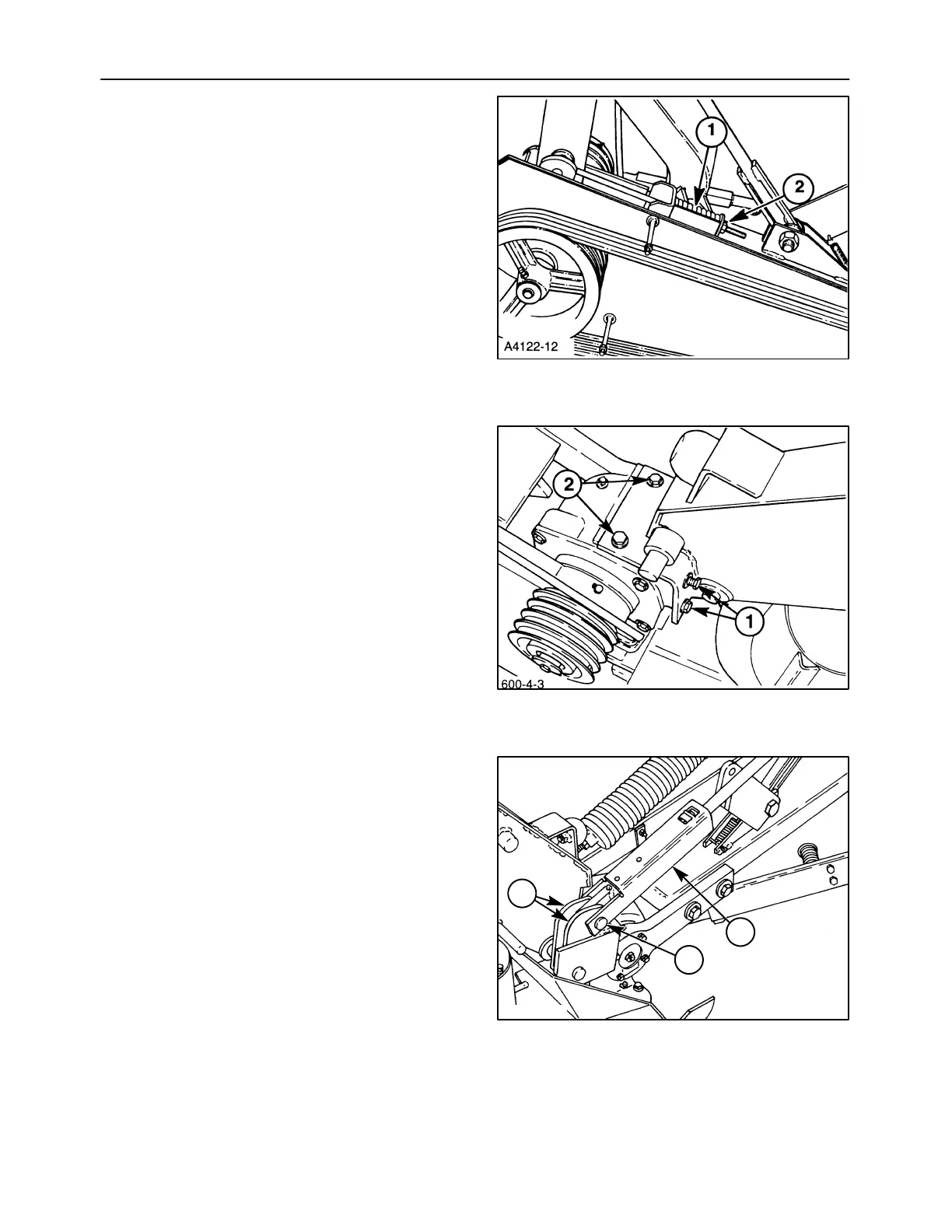
9. The mounting surface under the canopy support
of paint and dirt.
Attach a hoist or other lifting mechanism to the
canopy support as previously described, position
it onto the bevel gearbox, and install the six cap
screws and hardened washers. Tighten all
hardware finger tight, and torque the four cap
screws, 1, on the side of the gearbox to 159 N⋅m
(117 lb ft). After the cap screws on the side of the
gearbox are tight, tighten the remaining two cap
screws, 2, on the top of the gearbox to 159 N⋅m
(117 lb ft).
NOTICE: The four cap screws on the side of the
gearbox must be torqued before the top cap screws,
to ensure both sides of the canopy support mount are
tight against the gearbox.
10. Reattach the cylinder rod to the lift links by
positioning it between the links, 3. Install the lift
stop channel, 2, over the cylinder rod, and install
the shoulder pin, 1, and cotter pin.
29
30
A3671-10
1
2
3
31