SECTION 58 - DRIVELINES - CHAPTER 2
58-15
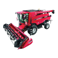
11. Raise the cutter bar high enough so that blocks
may be positioned under the #1 and end disc
modules, to support the cutter bar of f the floor.
Remove the three cap screws, 1, from the front of
the bevel gearbox, and slide the front lip of the
inner skid shoe, 3, on over the front of the bevel
gearbox and drive module. Reinstall the three cap
screws, 1, but do not tighten at this time. Attach
the inner shield, 4, and pipe support to the front of
the skid shoe using a carriage bolt, 2, and flange
nut.
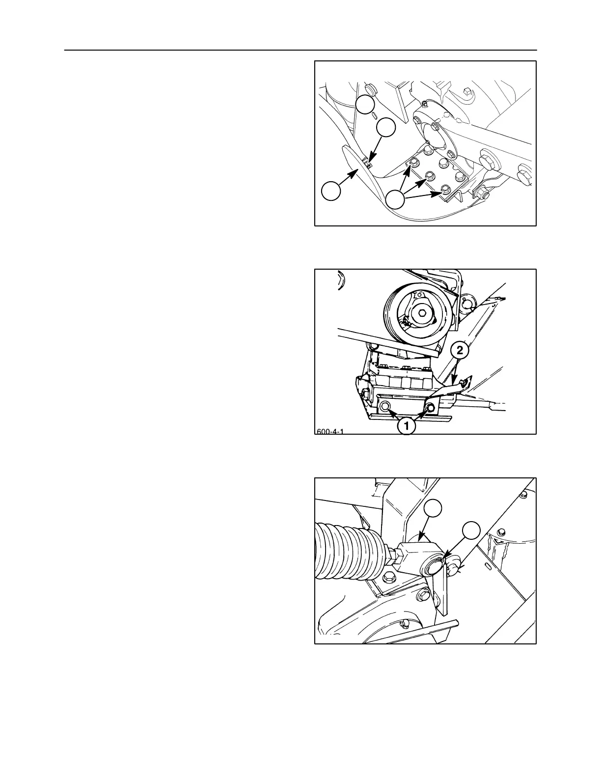
12. Install the two cap screws, 1, and lock washers to
secure the rear of the inner skid shoe to the drive
module; position the inner shield mounting
bracket, 2, under the right cap screw. Tighten the
two rear cap screws to113 N⋅m ( 83 lb ft). After the
two rear cap screws are tightened, torque the
three front cap screws, 1, Figure 32, to 159 N⋅m
(117 lb ft).
13. Install the flotation spring by sliding the lower
mount, 2, over the mounting pin; secure using a
flat washer and snap ring, 1.
19990604
2
4
3
1
32
33
600-4-2
1
2
34