0-8
STEERING
SYSTEM
1650K
TABLES
OF
TECHNICAL DATA
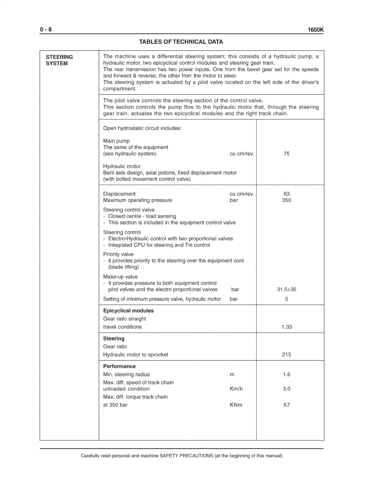
The machine uses a differential steering system; this consists of a hydraulic pump, a
hydraulic motor, two epicyclical control modules and steering gear train.
The rear transmission
has
two power inputs. One from the bevel gear set for the speeds
and forward
& reverse, the other from the motor to steer.
The steering system is actuated by a pilot valve located
on
the left side of the driver's
compartment.
The pilot valve controls the steering section of the control valve.
This section controls the pump flow to the hydraulic motor that, through the steering
gear train, actuates the two epicyclical modules and the right track chain.
Open hydrostatic circuit includes:
Main pump
The same of the equipment
(see hydraulic system)
Hydraulic motor
cu
cm/rev
Bent axle design, axial pistons, fixed displacement motor
(with bolted movement control valve)
Displacement
Maximum operating pressure
Steering control valve
- Closed centre - load sensing
cu
cm/rev
bar
- This section
is
included
in
the equipment control valve
Steering control
- Electro-Hydraulic control with two proportional valves
- Integrated
CPU
for steering
and
Tm
control
Priority valve
-
it
provides priority to the steering over the equipment cont
(blade lifting)
Make-up valve
-
It
provides pressure to both equipment control
pilot valves
and
the electro proportional valves bar
Setting
of
minimum pressure
valve,
hydraulic motor bar
Epicyclical modules
Gear ratio straight
travel conditions
Steering
Gear ratio
Hydraulic motor to sprocket
Performance
Min. steering radius
Max. diff. speed of track chain
unloaded condition
Max. diff. torque track chain
at 350 bar
m
Km/h
KNm
75
63
350
31.5+35
5
1.33
215
1.6
3.0
57
Carefully read personal and machine SAFETY PRECAUTIONS (at the beginning of this manual)