Figure 128
Figure 129
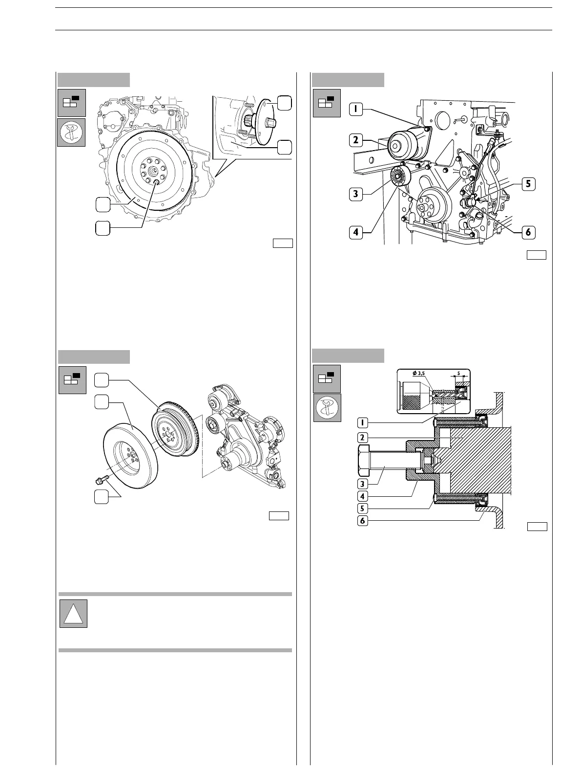
-
Use the 380000988 tool (2) to operate on the flywheel
cover box (1) in order to block flywheel rotation (3).
(Utilise starter holding down stu ds and fixing screw
nuts).
- Loosen the flywheel fixing screws (4) to engine drive
shaft.
Figure 130
- Remove the engine drive shaft fixing rin g from t he front
cover. Use the tool 380000665 (4) to operate on the front
tang (2) of the engine drive shaft. Throughout the tool
guide ports, drill the internal holding r ing (1) using Ø 3,5
mm drill for a 5mm depth. Fix the tool to the ring
tightening the 6 screws specially provided.
Proceed withdrawing the ring (1) tightening the screw
(3).
- Remove the screws (1) and disconnect the water pump
(2).
- Remove the screw (3) and the roller (4).
- Remove the screw (5) and disconnect the engine speed
sensor (6).
Figure 131
00900t
75692
3
4
1
2
70148
!
In same versions, the phonic wheel to be assembled
to the pulley (1) cannot be provided along with the
equipment.
1
2
3
74175
- Unloose the screws (3) and disassemble the damping
flywheel (2) and the pulley (1).
SECTION 3 − DUTY − INDUSTRIAL APPLICATION E NG I NE S
45
ED. FEBUARY 2003
zs