Figure 132
Figure 133
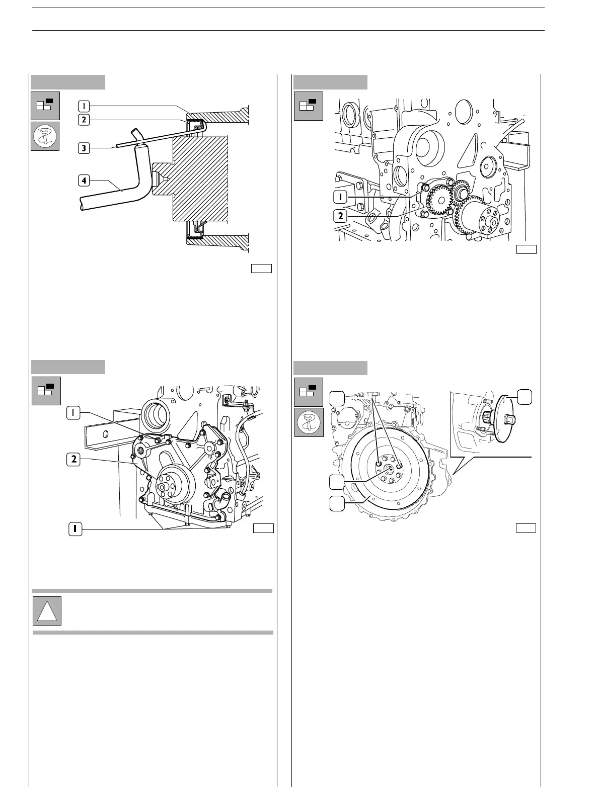
-
Use acceptable tools (3) (4) and withdraw the external
holding ring (2) from the front cover (I).
- Loosen the screws (1) and remove the front cover (2).
Figure 134
- Screw out the opposite screws (1) from t he ports wh ere
the withdr awal pins shall be introduced (see picture
following).
- Loosen remaining flywheel fixing screws (3) to the
engine drive shaft (4).
- Remove the flywheel block tool (2).
- Loosen the screws (1) and remove oil pump (2).
Figure 135
75688
70149
!
Take note of the screw (1) assembly position, since
the screws have different length.
75811
1
2
3
4
75691
SECTION 3 − DUTY − INDUSTRIAL APPLICATION
46
E NG I NE S
ED. FEBUARY 2003
zs