3. ATTACHMENT DIMENSIONS
3-3
3
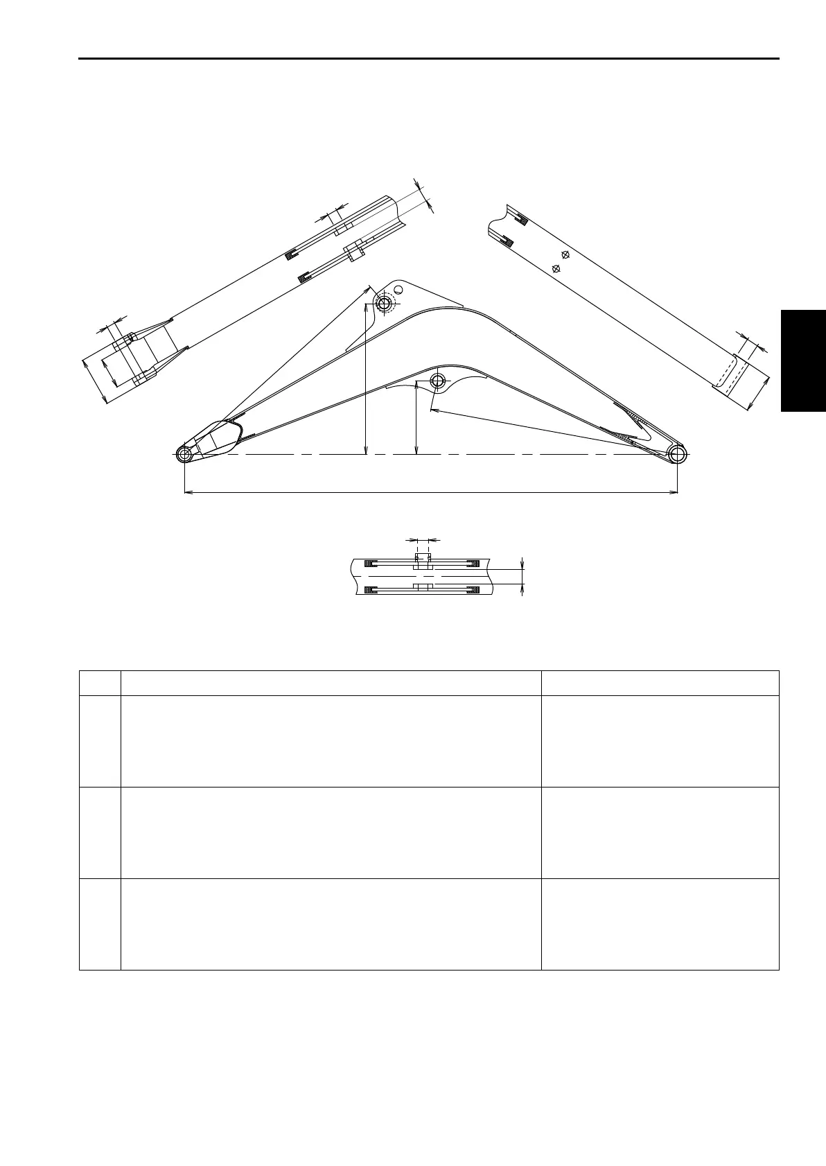
3.1 BOOM
3.1.1 BOOM DIMENSIONAL DRAWINGS
Boom Dimensional Drawings
No. NAME DIMENSIONS [mm(ft-in)]
A
B
C
D
E
Boom length
Distance between pins of boss
Distance between pins of bracket
Height of boom cylinder rod pin
Height of arm cylinder (head side) pin
1750 (5'8.90")
R890.5 (R2'11.06")
R887.5 (R2'10.94")
261 (10.28")
535 (1'9.06")
F
G
H
J
K
Boom foot width
Inner width of bracket for boom cylinder (rod side) mounting
Boom end inner width
Boom end outer width
Inner width of bracket for arm cylinder (head side)
140 (5.51")
51 (2.01")
110 (4.33")
176 (6.93")
51 (2.01")
d1
d2
d3
d4
Boom foot pin dia.
[Bushing outer dia.]
Boom cylinder (rod side) pin dia.
Pin dia. of arm end
Arm cylinder (head side) pin dia.
35 dia. (1.38")
[45 dia. (1.77")]
35 dia. (1.38")
30 dia. (1.18")
35 dia. (1.38")