— 9 —
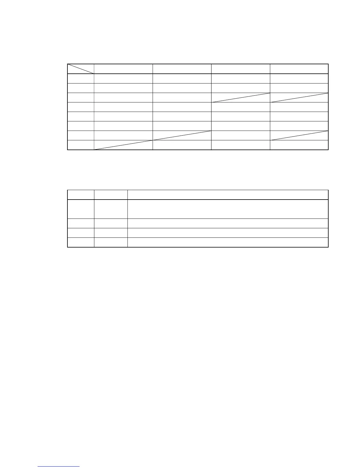
BUTTON MATRIX
POWER SUPPLY CIRCUIT
The power supply circuit generates four voltages as shown in the following table.
KI0 KI1 KI2 KI3
L18 STEP BY STEP PART L PART R NEXT
L19 TOUCH SELECT TRACK A TRACK B PLAY/STOP
L20
TEMPO/BEAT/FIXED
METRONOME
L24 PIANO 2 E. PIANO HARPSICHORD W.BASS
L25 PIANO 1 STRINGS CHOIR E.BASS
L26 VIBRAPHONE PIPEORGAN
CHORUS/TREMOLO
REVERB
L27 SONG SELECT RECORD
L28 VALUE DOWN VALUE UP DEMO
Name Voltage For operation of
VDD +5 V CPU, Reset IC, Working storage RAM, DSP, Key touch LSI, Sound source
ROM, Effect RAM, Gate array
AVDD +5 V DAC
AVCC +15 V Filter, Mixer
AVFF –15 V Filter, Mixer