— 11 —
4-3. Adjustment method
4-3-1. Preparations
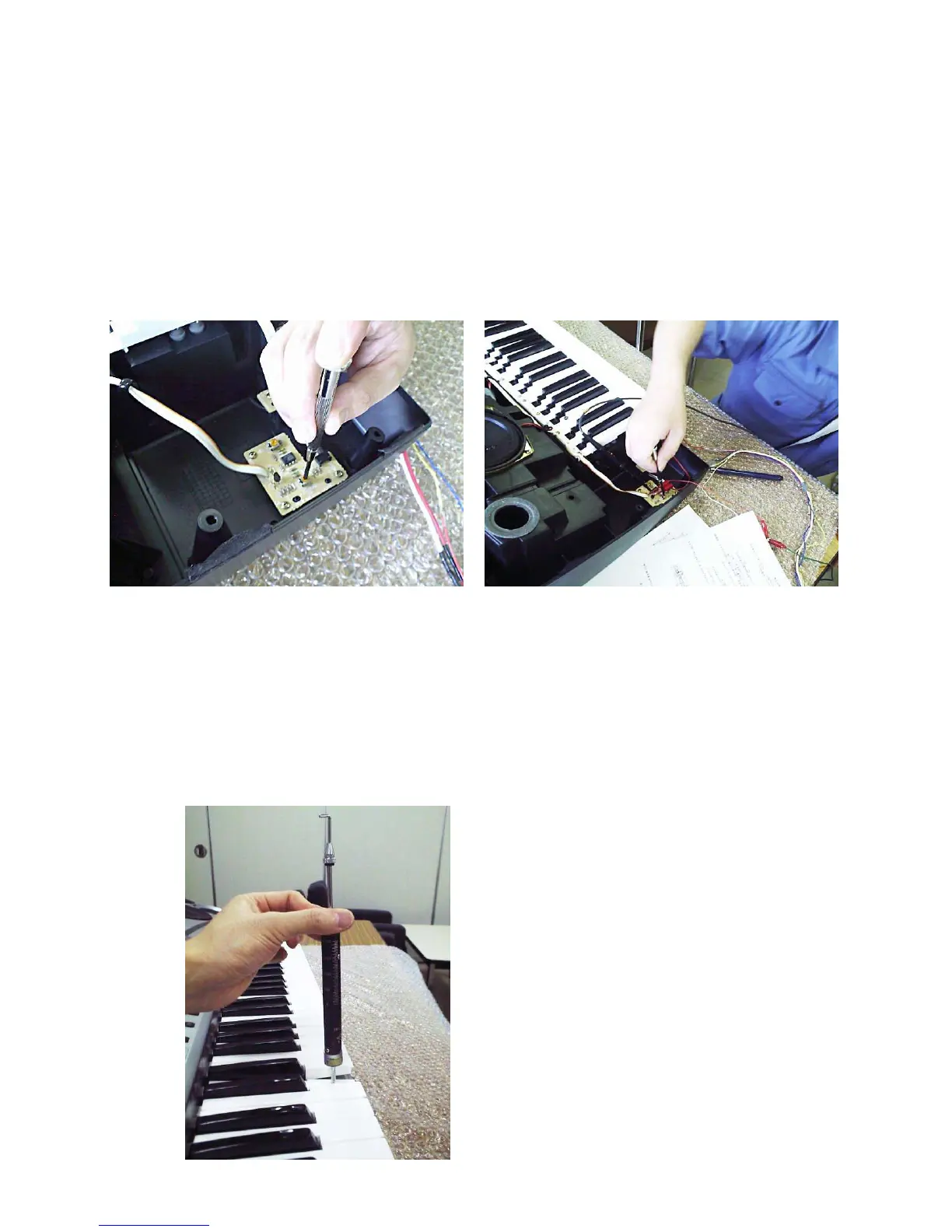
1) Turn adjustment VR’s VR951 (OFFSET) and VR952 (GAIN) on PCB SN1M counterclockwise
(Fig. 4).
2) Connect voltage regulator to pin numbers 1 (GND) and 3 (AVCC source) on PCB SN1M’s CH
joiner and provide 13.6 V (+/-5%) voltage.
3) Connect oscilloscope on pin numbers 1 (GND) and 2 (output voltage).
4) Turn VR951 clockwise and adjust output voltage for about 800 mV (Fig. 5).
5) Turn VR952 clockwise and adjust output voltage for about 500 mV (VA).
FIG.4 FIg.5
4-3-2. White key measurement
1) Before the measurement, press all of the 36 white keys with about 1,000 grams pressure.
2) Observing the oscilloscope, apply 1,500 grams pressure at adjustment point (2 cm from the
edge) on the 32 white keys E1 – A5 (do not use two each of either ends as the adjustment key)
and find the key whose voltage change is minimum (the key becomes adjustment key). It is
preferable to use a push-pull gauge (Fig. 6).
3) After determining adjustment key, apply 1,500 grams pressure on the adjustment key and
record the output voltage (VC).
FIG.6