— 10 —
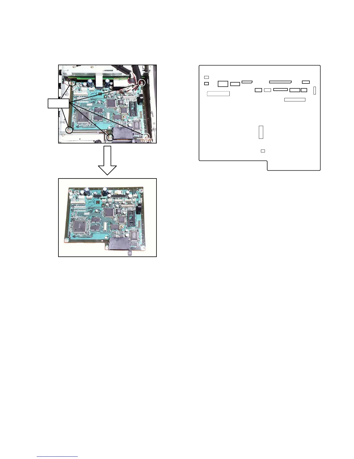
■ MAIN PCB
1. Remove the upper cover as shown in steps 1 to 3 of page 9.
2. Remove the seven connectors (CN13, CN14, CN15, CN11, CN9, CN8, CN7, CN18), two FPCs (CN16,
CN17) and five screws, and then the MAIN PCB.
CN13
CN15
CN16
CN11 CN10
CN17
CN18
CN9 CN7CN8
CN5
CN6
CN14
CN12
CN3
CN2
CN19
Screws
 Loading...