Do you have a question about the Casio V-R200 and is the answer not in the manual?
Details critical safety warnings, including battery handling and general cautions for device operation.
Provides guidelines for proper installation location and general handling to prevent malfunction or damage.
Explains device states (OFF, ON, Sleep) and general operational information.
Covers recommended memory cards, mounting, and unmounting procedures.
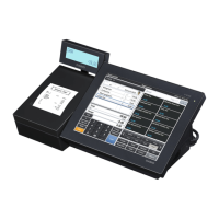
A detailed list of technical specifications for the device's main display, touch panel, printer, and other components.
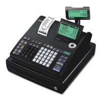
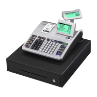
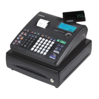
Identifies and describes the functions of major components visible on the front and rear of the device.
Lists available optional devices and various drawer models with their specifications.
Introduces the hardware testing section, listing various tests for device components.
Details how to check the OS version and perform an operating system update procedure.
Critical warnings on static electricity, tool usage, and general handling during disassembly.
A visual guide to different screw types used in the device for correct reassembly.
Step-by-step instructions for removing and replacing the main Printed Circuit Board.
Detailed guide for removing and replacing the LCD screen assembly.
Instructions for disassembling and replacing the Input/Output Controller Assembly.
Procedure for removing and replacing the secondary customer display.
Steps for removing and replacing the internal motor component.
Detailed guide for removing and replacing the integrated printer unit.
Procedures for replacing specific internal cables, including IOC PCB connections.
Instructions for replacing various other external and internal parts like cases and chassis.
A high-level diagram illustrating the main system components and their interconnections.
Detailed diagrams showing the component layout for the E843-1 PCB.
An illustrated breakdown of the main unit with a comprehensive list of all parts.
Detailed exploded view and parts list specific to the display assembly.
Exploded view and parts list for various internal cables used in the device.
Illustrated overview and parts list for optional accessories.
| Display Type | LCD |
|---|---|
| Card Reader | Optional |
| Paper Width | 58mm |
| Power Source | AC Adapter |
| Touch Panel | Yes |
| Screen Size | 10.4 inch |
| Operating System | Android |
| Connectivity | Ethernet |
| USB Ports | USB 2.0 |
| Printer | Thermal printer |
| Dimensions | 395mm x 237mm x 229mm |