— 30 —
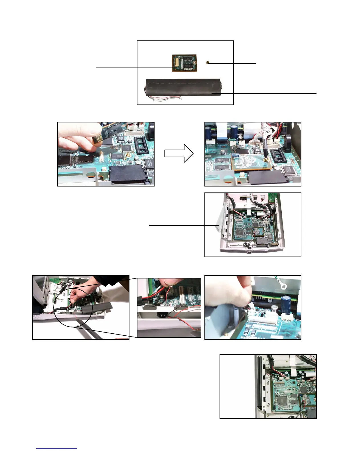
6-4. MEMORY PCB
1. Remove the upper cover as shown in steps 1 to 3 of page 9.
2. Fix the additional memory to the MAIN PCB (CN3) with a screw.
3. Remove the UL tube from the ECR.
4. Let the power cord of the BACKUP BATTERY through the hole on the side of the ECR and fix it to the MAIN
PCB (CN19).
Note: Insert two BACKUP BATTERIES together.
Main memory
Backup battery for additional
memory
Screw
UL tube (Clear type)
 Loading...