— 26 —
4-5. Color adjustment
1. Adjustment procedure
• Make sure
VCC5 (CP344) = 5.0 ± 0.05 [V]
VCC15 (CP391) = 15.0 ± 0.45 [V]
VCC7 (CP390) = 8.0 ± 0.05 [V]
VCC3 (CP220) = 3.3 ± 0.08 [V]
• Perform this adjustment after Contrast adjustment.
2. Preparation
• AC adaptor or voltage regulator
• Frequency counter
3. Adjustment and checking
(1) Turn the power on while pressing SHIFT and MENU keys simultaneously. (TEST MODE)
(2) Push SHIFT ➜ SHIFT ➜ MENU keys in order rapidly. (TEST MODE 1)
(3) Select and execute COLOR BAR.
(4) Trigger with FRP (CP305) signal.
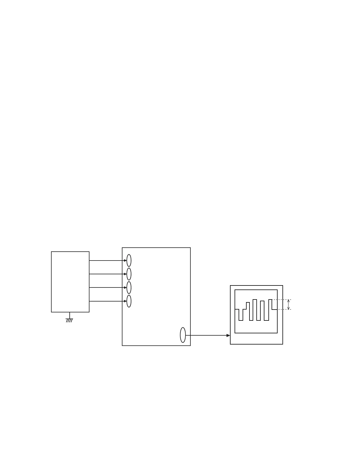
(5) Adjust VR300 so that pulse width of 4th VB waveform (CP324) (pedestal-peak) is 2.90 ± 0.05Vp-p.
(6) Proceed to TINT adjustment.
4. Note
Perform the adjustment after (continuously from) Color adjustment.
D-PCB
VCC15
(CP391)
VCC5
(CP344)
VCC7
(CP390)
VCC3
(CP220)
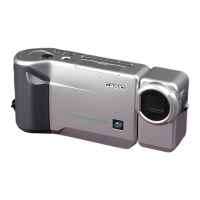
QV-3500EX
2.90 ± 0.05 [Vp-p]
VB(CP324)
1432
Digital oscilloscope
Power
Supply
 Loading...