— 8 —
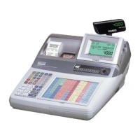
■MAIN DISPLAY
1. Remove the upper cover as shown in steps 1 to 3 of page 5.
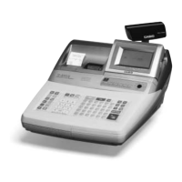
2. Remove two FPCs (CN101, CN102).
3. Remove four hooks and the MAIN DISPLAY.
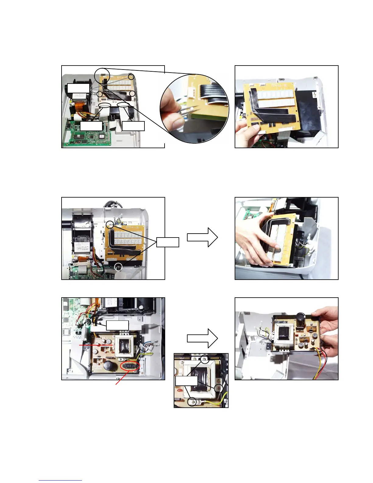
■POWER SUPPLY UNIT
1. Remove the upper cover as shown in steps 1 to 3 of page 5.
2. Remove two FPCs (CN101, 102)
3. Remove two screws.
4. Remove the Main display with the upper case of the Power supply.
5. Remove one connector (CN5) and three screws, and then the power unit.
Screws
CN102CN101
Hooks
CN5
Screws
F1
Voltage selector switch
Nomally, Do not change the voltage
position
 Loading...