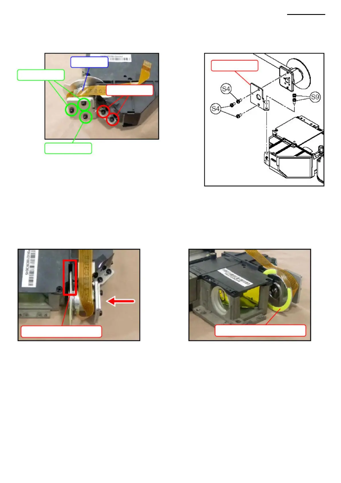
H. MODULE FW H-1.
Unscrew the two screws (S9) and remove the FW module together with the corner plate. H-2.
Unscrew the three screws (S4) and remove the FW module.
Screws (S4)
FW module
<ASSEMBLY NOTES: FW MODULE>
Angle plate
Screws (S4)
With the FW module aligned with the corner plate, follow the steps below to assemble the FW module. • Insert a feeler
gauge (0.03 mm) between the wheel (color plate) and the frame. While pressing the FW module in the direction of the arrow,
tighten the two screws (S9). NOTE: be careful not to
damage the wheel. NOTE: Do not push the FW module too hard.
This may make it impossible to remove the dipstick.
XJ-A240/A245
Insert probe
Screws (S9)
Color plate (yellow part)
-25-
Machine Translated by Google
 Loading...