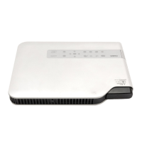
L. PWB-3 L-1. Disconnect
connectors.
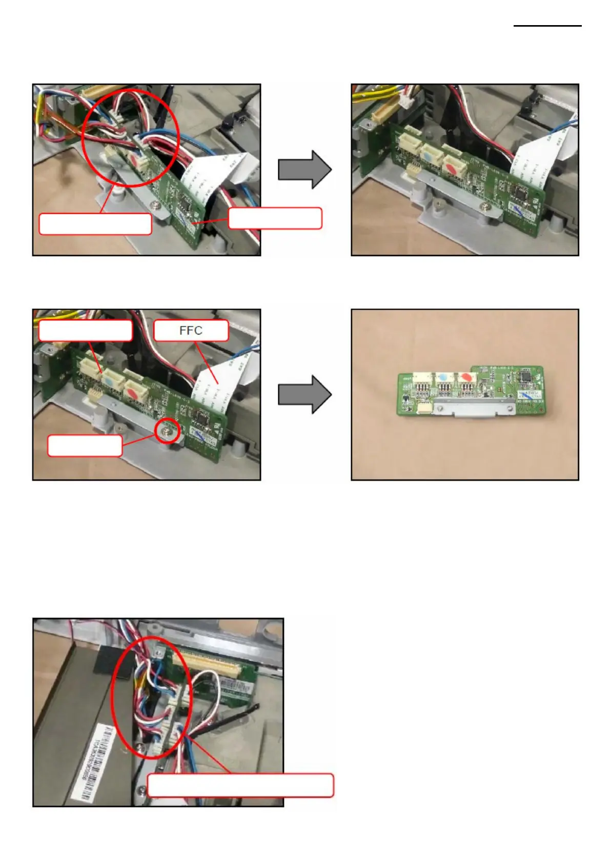
Salary PWB-3
NOTE: run cables (FAN MODULE A) between PWB-3 board and LSA-M module.
Salary PWB-3
• When assembling the PWB-3 board, make sure the cables are routed according to the following.
Screw
Five connectors
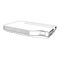
L-2. Unscrew one screw and remove the PWB-3 board.
<ASSEMBLY NOTES: PWB-3 BOARD>
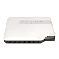
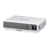
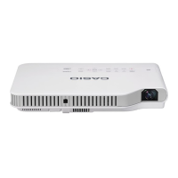
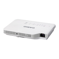
XJ-A240/A245
• Before assembling the PWB-3 board, connect the FFC cable. • When
connecting the connectors (FAN MODULE B), make sure to connect
L-3. Remove the FFC cable.
pattern.
the corresponding connector.
NOTE: For a more detailed description, see <ASSEMBLY NOTES>, subsection “J. FAN MODULE A".
Connectors (FAN MODULE A)
-32-
Machine Translated by Google
 Loading...