-7-
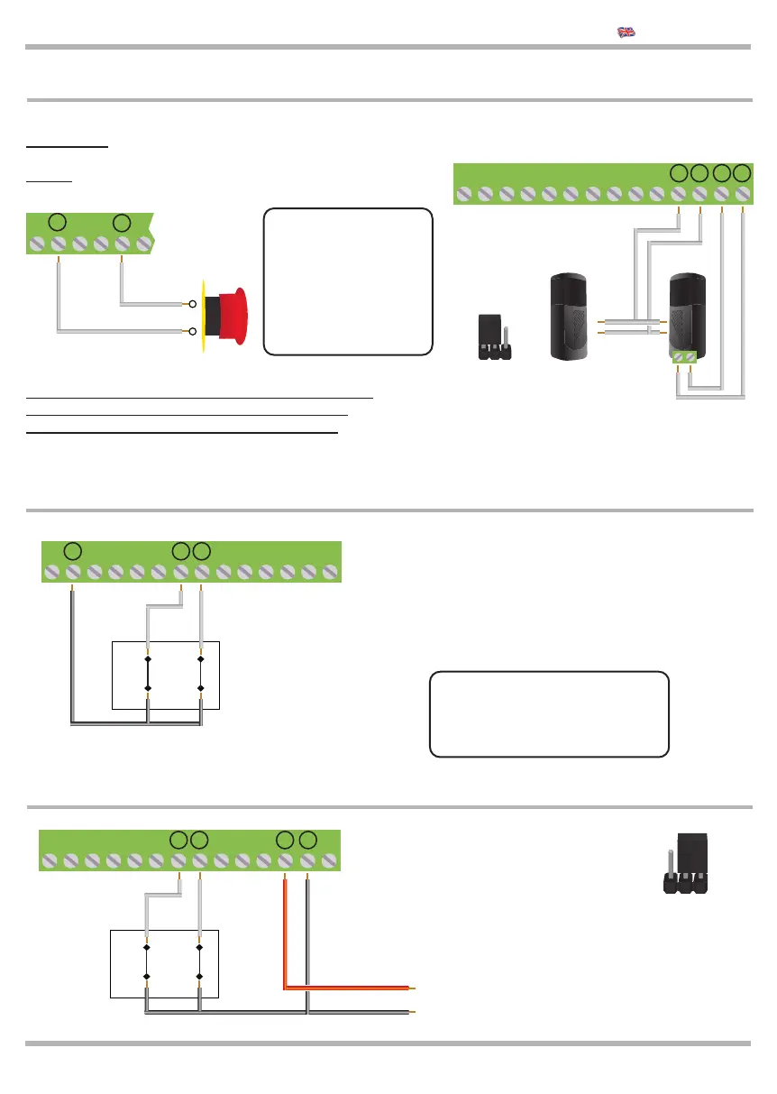
2.7 Connection of the STOP and PHOTO 2
Connection of the safety devices requires the use of
any push-button or N.C. (normally closed) contact.
If more devices are available, connect in parallel.
2.8 Connection of LIMIT SWITCHES LSO and LSC
The picture shows the connection of both limit
switches, however, on this control unit they can be
used separately. The limit switch contacts must be
N.C. (normally closed) contacts.
If the LSO or LSC
inputs aren’t used:
put the ON DIP3B for LSO
put the ON DIP4B for LSC
!
2.9 Connection of the MAGNETIC LIMIT SWITCHES
JUMPER AC/DC
Power Supply
magnetic limit
switches
24 Vdc
Bring the
Jumper in DC
8 9 10 11 12 13 14 15 16 17 18 19
8 9 10 11 12 13 14 15 16 17 18 19
OPEN
N.C.
CLOSE
N.C.
LIMIT
SWITCHES
OPEN
N.C.
CLOSE
N.C.
LIMIT
SWITCHES
KEQS08
Technical Manual
8 9 10 11 12 13
Connection of the STOP control
Push-button: stops and temporarily prevents all
control unit function until it is pressed again.
Switch: keeps the automation blocked until the
swicht will be activated again.
If the STOP input
is NOT used put
the DIP 1B on
ON. If the input
PHOTO 2 is not
used, put the DIP
5B on ON.
!
20 21
20 21
Connection of the PHOTO2 control:
For operation see DIP 6 A page. 11
RX
TX
Contact NC
8 9 10 11 12 13 14 15 16 17 18 19
24 Vac
AC DC
Set the
JUMPER
JAC/DC
as in the
picture
20 21