Check Method of Causes
Explanation Figures
Repair Method
Cateye Ergociser EC-5000 Service Manual
15
No Display of Heart Rate (The case with Wireless Chestbelt Pulse Sensor Kit) (1)
T-4
No Display of Heart Rate (The case with Wireless Chestbelt Pulse Sensor Kit) (1)
18 27
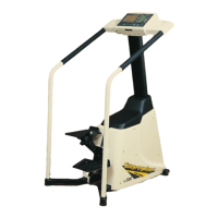
Fig.1
Control Unit
Tapping Screw
Cable Connector
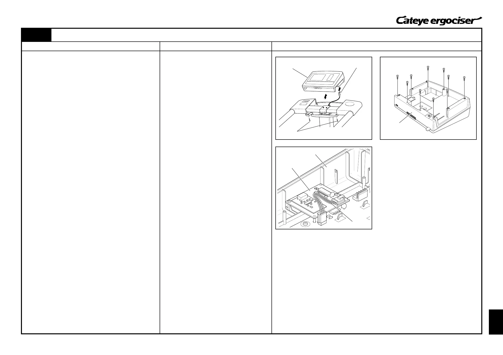
Control Unit
Control Unit
Receiver Board
Connector Cable
First, check the items as described in the section [Trouble-Shooting
and Handling Care] of the Operating Instructions which comes with
the Wireless Chestbelt Pulse Sensor Kit.
When the symptom does not go with those items, proceed to the
following checks.
[1] Checking the Wireless Chestbelt Pulse Sensor
1. Turn on the power to display the in-training screen (any exer-
cise program).
2. Install a new transmitter on the chestbelt as described in the
operating Instructions for the Wireless Chestbelt Pulse Sensor
Kit.
Check if your pulse rate will be displayed.
[Judgment]
ⓦ When the heart rate can be displayed, the previous trans-
mitter might be defective. In this case, you need to take
actions as specified in the repair method (a) described at
the right.
When the heart rate cannot be displayed, proceed to the following
checks.
[2] Checking the Receiver Board
1. Turn off the power of the main unit.
2. Remove seven tapping screws on the control unit cover and
detach the control unit. (Fig. 1)
3. Disconnect the cable connector, which is at the tip of the 5P
cable, from the cable inlet at the back of the control unit. (Fig.
1)
4. Remove ten screws at the back of the control unit and remove
the rear panel of the control unit. (Fig. 2)
5. Check that connectors at both ends of the connector cable
which connects the receiver board and the board within the
control panel are not disconnected from respective boards.
(Fig. 3)
[Judgment]
ⓦ The disconnected connectors are the possible cause of the
problem.
In this case, you need to take actions as specified in the
repair method (b) described at the right.
When the connector cable is correctly connected, proceed to the
procedures as described in the next page.
(a) Replace the transmitter.
(b) Firmly connect the connector cable to the connec-
tors of both the receiver board and the control unit.
Fig.2
Fig.3