Check Method of Causes Repair Method
Explanation Figures
Cateye Ergociser EC-5000 Service Manual
20
No Cadence Control (Faster cadence control is not possible.) (1)
T-6-2
No Cadence Control (Faster cadence control is not possible.) (1)
T-6-2
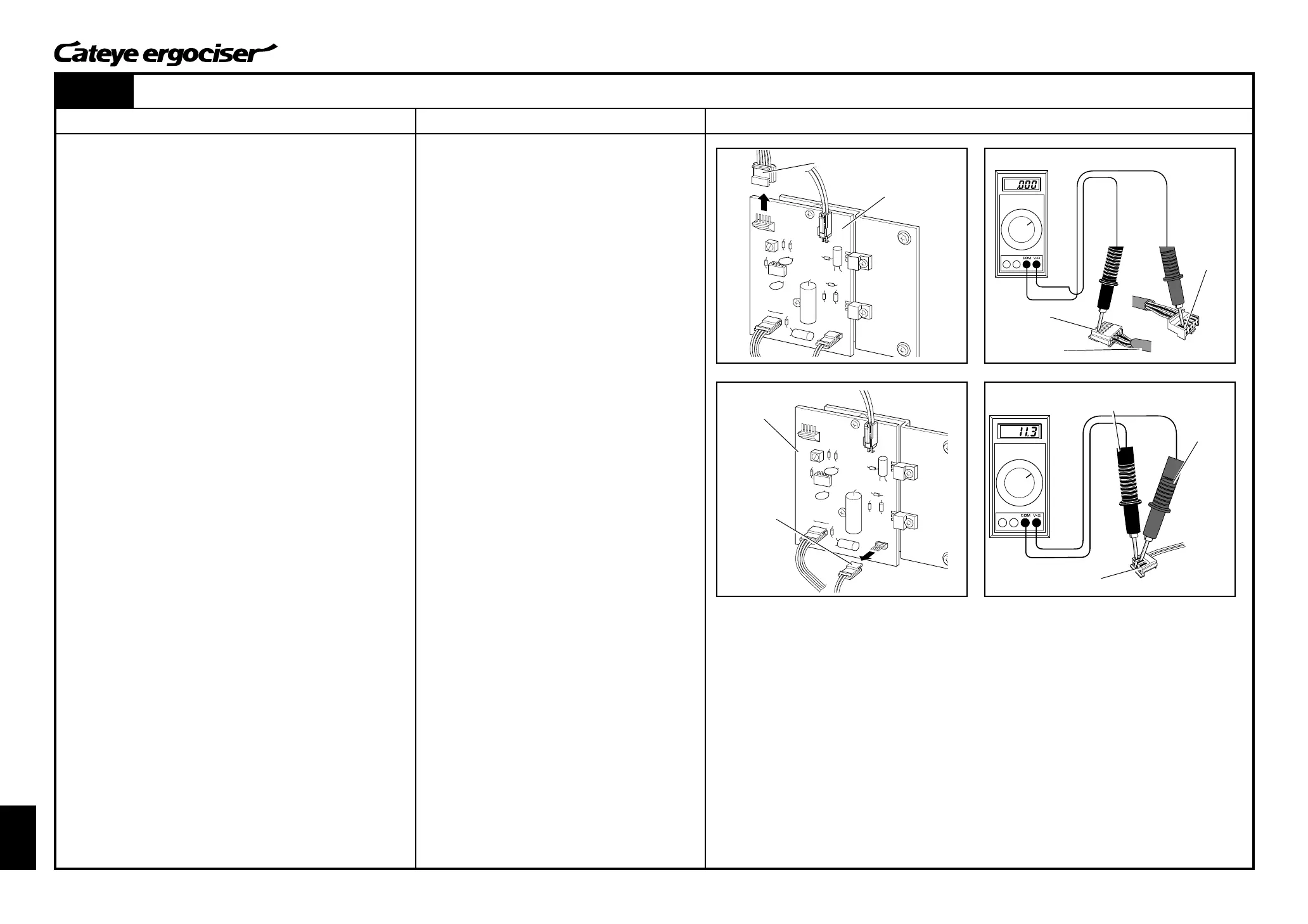
Fig.1
5P Connector
3P Connector
Normal for 14V thru 19V
(a) Replace the control unit with a new one.
(See [ES-9: Replacing the Control Unit].)
Power Supply Board
[1] Checking the Control Unit
1. Replace the control unit with a new one.
(See [ES-9: Replacing the Control Unit].)
2. Check if the cadence can be changed (to faster rate) under the
manual training mode.
The check should be made by using a training mode which
provides frequent change in cadence.
[Judgment]
ⓦ When the cadence changes correctly, the previous control
unit might be defective. In this case, you need to take ac-
tions as specified in the repair method (a) described at the
right.
When no cadence change is noted, proceed to the following proce-
dures.
[2] Checking the 5P Cable
1. Turn off the power of the main unit, and remove the cover of
the main unit set.
(See [D-1: Removing the Frame Covers].)
2. Remove the 5P connector at the power supply board. (Fig. 1)
3. Check any short-circuiting across the two connectors (Termi-
nal 1s) at both ends of the 5P cable. (Fig. 2)
When there is a short-circuiting, the tester reading will be zero (0).
[Judgment]
ⓦ When there is no short-circuiting, the 5P cable might be
disconnected.
In this case, you need to take actions as specified in the
repair method (b) described at the right.
When there is short-circuiting, proceed to the following procedures.
[3] Checking the 3P Connector
1. Remove the 3P connector at the power supply board. (Fig. 3)
2. Measure the resistance by using a tester across Terminals 1
and 2 on the 3P connector. (Fig. 4)
[Judgment]
ⓦ When the measured resistance is in the range of 9- to 14-
ohms, the 3P connector is normal but the power supply
board might be defective. In this case, you need to take
actions as specified in the repair method (c) described at
the right.
ⓦ In case the measured resistance is excessively large, the
solenoid coil might be defective. In this case, you need to
take actions as specified in the repair method (d) described
at the right.
(b) Replace the 5P cable.
(See [ES-2: Replacing the 5P Cable].)
(c) Replace the power supply board.
(See [ES-3: Replacing the Power Supply Board].)
(d) Replace the solenoid coil set.
(See [ES-5: Replacing the Solenoid Coil Set].)
Power Supply
Board
3P Connector
Black Cable
(Terminal 1)
Red Cable
(Terminal 2)
The case a short-circuiting is found:0/no short-circuiting:1.
Black Cable
(Terminal 1)
Red Cable
(Terminal 1)
5P Cable
Fig.2
Fig.3
Fig.4