Cateye Ergociser EC-5000 Service Manual
35
Replacing the CDC Sensor Set
ES-6
Replacing the CDC Sensor Set
ES-6
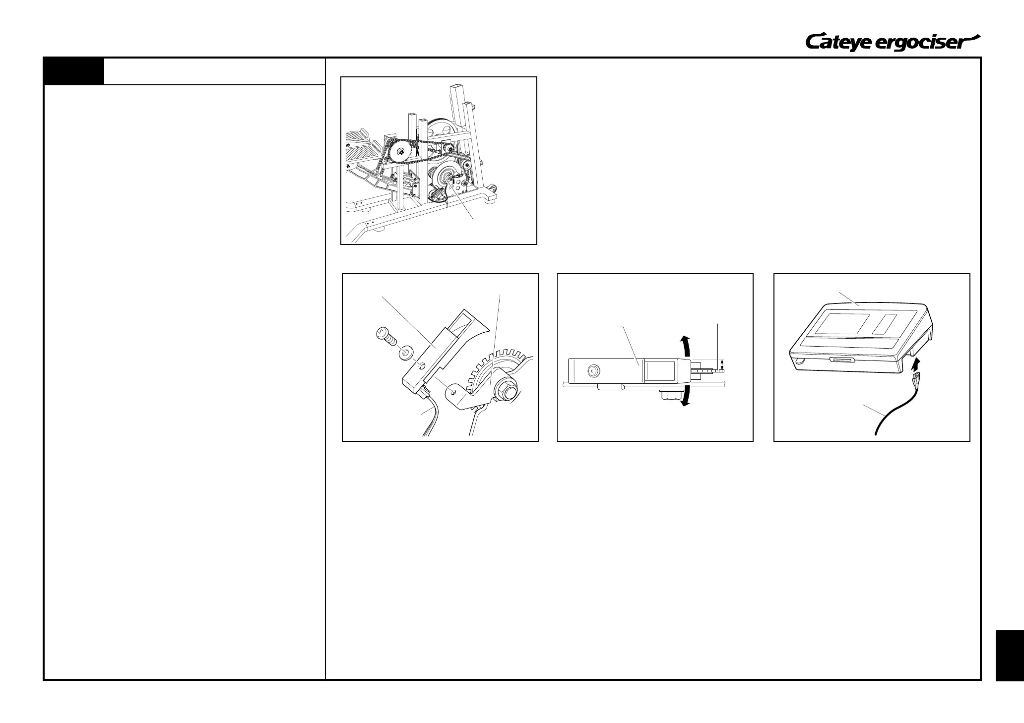
General Figure
CDC Sensor Set
CDC Sensor Set
CDC Sensor Cable
Parallel
Turn Board
CDC Sensor
Control Unit
5P Cable
REMOVAL
1. Detach the frame cover.
(See [D-1: Removing the Frame Covers].)
2. Detach the CDC sensor set by loosening screws. (Fig. 1)
3. Detach the CDC sensor cable from the CDC sensor set.
ASSEMBLE
1. Connect the CDC sensor cable to a new CDC sensor set, and
then mount it to the CDC sensor metal base. (Fig. 1)
2. Adjust the position of the CDC sensor.
A.Rotate the CDC sensor around the screw. (Fig. 2)
B.Rotate the CDC sensor around the screw, and adjust the
sensor so that it can be positioned to parallel with the CDC
magnet with the condition that the sensor does not touch the
magnet. (Fig. 2)
3. Perform tests on the parts as specified for mounting and re-
placing the parts.
[Tests]
A.Connect the control unit and the 5P cable without mounting
the cover. (Fig. 3)
B.Turn on the power of the main unit, and rotate the pedal
under the manual training mode to check that the cadence
on the control unit will change.
C.Then, turn off the power and detach the 5P cable from the
control unit.
4. Assemble the frame cover.
(See [D-2: Mounting the Frame Covers].)
CDC Sensor Metal Base
Fig.1
Fig.2