Front Panel LEDs and Reset Buttons (X1700B)
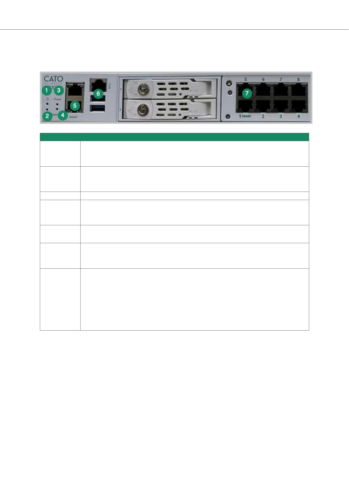
This section explains the LEDs and reset buttons on the front panel of the X1700B Socket.
Item Description
1 Power LED
• off - the Socket is powered off
• on - the Socket is powered on
2 HDD LED
• off - the HDD for the Socket is currently inactive
• on (blinking) - the Socket is accessing data on the HDD
3 Power button - Powers on & off the Socket
4 Reset button - resets the Socket
• Reset Socket WebUI password - press for 5 - 15 seconds
• Reset to factory default settings - press for 25 - 35 seconds
5 MGMT port - connects to the Socket WebUI
Note: Only the lower port is the MGMT port
6 COM and USB ports
• COM port - console port (used by Support to troubleshoot Socket)
• USB ports - you can use USB 2.0 or 1.0 flash drives to reimage the X1700B Socket
7 LEDs for network ports
• Left LED (activity)
◦ no color - port link is disconnected
◦ green (steady color) - link has connectivity
◦ green (blinking) - link is active and passing traffic
• Right LED (link speed)
◦ no color - link speed is 10 Mbit/s
◦ green - link speed is 100 Mbit/s
◦ amber - link speed is 1000 Mbit/s
Connecting the X1700 Socket to the Cato Cloud
Connect the LAN and WAN ports on the X1700 front panel to the internal network and to the ISP.
These instructions apply to all X1700 Socket models.
1. Unbox the Socket.
2. Connect the LAN cables:
• If the Socket is replacing a firewall , disconnect the Ethernet cable from the firewall and connect
the cable to the Socket’s Port 3.
• If the LAN is routed from a network device or existing firewall that is not being replaced, connect
the Ethernet cable from the relevant port on that device to the Socket’s port 3.
3. Connect the WAN cables:
• If the Socket is connected directly to the ISP router, connect the Ethernet cable from the ISP
device to the Socket’s port 1 (or port 1 and port 2 if you have multiple ISP connections).
Socket X1700 Deployment Guide Deploying Your Cato Socket
Page 11 of 18