Do you have a question about the Cavli Wireless C10QM and is the answer not in the manual?
Familiarizes the reader with the functionalities and interfaces of the evaluation board.
Lists the documents the present document is based on.
Details necessary information on C10QM/C20QM EVK Interfaces and Pin-outs.
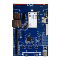
Provides a visual representation of the C10QM/C20QM EVK board layout.
Details the pinout configuration for the C10QM/C20QM EVK.
Details the integrated LTE, diversity, and GNSS antennas on the EVK.
Describes the integrated LTE antenna from Ignion, covering low, mid, and high bands.
Explains the integrated chip antenna for diversity and SMA connectors for external antennas.
Details connecting an external GNSS antenna via the U.FL connector.
Explains how to insert a SIM card into the micro-SIM socket.
Details the JTAG interface for module programming.
Describes the interface for accessing the SDC of the C10QM/C20QM.
Explains the micro-SD card socket for file access.
Details the LAN cable connection and Ethernet interface.
Describes the integrated AR8033 Ethernet transceiver and RJ45 interface.
Explains the MIPI DBI-2 Type B interface for LCD interfacing.
Details the various LED indicators on the EVK for status monitoring.
Indicates 3.8V power input status.
Indicates 3.3V power input status.
Indicates 1.8V voltage source status.
Indicates power status when LCD is enabled.
Indicates USIM selection status.
Indicates flight mode status.
Indicates WLAN status.
Indicates module status (on/off).
Indicates network connection status.
Indicates RESOUT_N status.
Indicates module wakeup state.
Details the FT4232 converter for USB-UART communication.
Explains access to interfaces via the 50-pin connector.
Describes the button used to enter the bootloader.
Explains the button used to reset the module.
Details the button used to power on the module.
Explains the switch for powering the EVK board on/off.
Recommends 5V/2A adapter or PC USB port for power input.
Details the micro-USB interface for USB 2.0 access.
Explains using USB cable for UART ports (debug, AT).
| Model | C10QM |
|---|---|
| Category | Control Unit |
| Connectivity | Cellular, GNSS |
| Processor | ARM Cortex-M4 |
| Operating Voltage | 3.3V - 4.2V |
| Operating Temperature | -40°C to +85°C |
| Weight | 10g |
| GNSS | GPS, GLONASS, BeiDou, Galileo |
| Interfaces | UART, I2C, SPI, GPIO |
| Certifications | CE, FCC, RoHS |