15
When is adapted according to the temperature
measured by the sensor.
connected, the charging voltage
Temperature sensor (mod. “C , where
it cannot be affected by other heat sources
TCB” L=3m) to be placed close to the battery
.
CONNECTION BATTERY TEMPERATURE SENSOR (optional)
9)
11)
10)
- Install the regulator in an appropriate dry and
ventilated housing; make sure there is a minimum
distance of mm from the front and mm from
the sides to the surrounding
surfaces.
200 20
of the device
- The regulator is not suitable for external use.
- Solar System cables should be placed far away
from the cables for Radio/TV/SAT antenna .s
- Connection to other equipment which can dama
ge correct operation may result in warranty
void.
-
its
- Do not cover air intakes on the lid.the
- Fasten the equipment with the screws on a flat
surface using the 4 holes on the base.
- he PR egulator is not suitable for the
charging of nickel/cadmium batteries, other kinds
of rechargeable or non rechargeable batteries not
outlined in this manual.
T M350 r
- Lead-acid batteries shall be positioned in a well
ventilated place.
- 10 mm (cable over 5m long)²
- Battery connection: use cables with adequate
section. Recommended sections:
- The produces heat during normal
operation. Make sure that the installation of other
equipment near the instrument does not hamper
the correct air flow and prevent the necessary
instrument cooling.
device its
- Protect the cable from any possible damage. s
- Protect the 12V battery line using a suitable fuse
to be placed close to the battery.
- Only connect specific lithium batteries for the
sector.
RV
- 6 mm (cable under 5m long)²
- nnect only 12V rechargeable lead
batteries (capacity >40Ah).
Co (6 cells)
OPERATING INSTRUCTIONS AND INSTALLATION
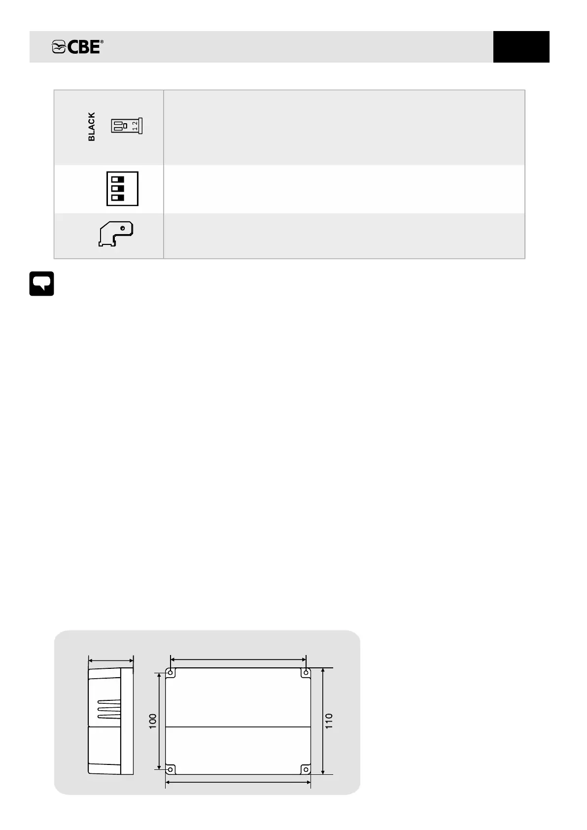
Pic. 1 - DIMENSIONS (mm):
6.3
Male faston type 6.3 for connection of the battery and the photovoltaic modules.
140
48
150
EN
CHARGE LINE SELECTOR.
BATTERY/ PHOTOVOLTAIC MODULES CONNECTION
3
2
1