16
cdvigroup.com
EN
ATRIUM
2-Door Controller
INSTALLATION MANUAL
EN
ATRIUM
2-Door Controller
INSTALLATION MANUAL
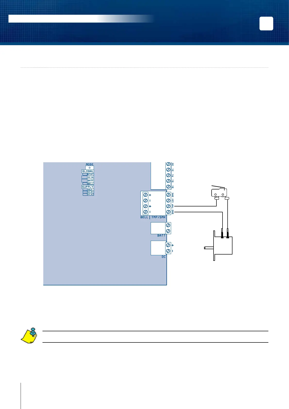
5] WIRING DIAGRAM
Connecting the tamper switches allows the 2-Door Controller to detect when the cabinet door is opened and/or
when the cabinet is removed from the wall. To install the tamper switches, see “Installing the Tamper Switches”.
To use both switches:
1. Connect one end of the supplied wire, the one with a log at each end, to the door tamper switch
terminal and the other end to the wall tamper switch terminal.
2. Connect the other terminal of the door tamper switch to the “TMP” terminals using the
supplied wire.
3. Connect the other terminal of the wall tamper switch to the “GND” terminals using the
supplied wire.
To use only one switch:
1. Connect one terminal of the tamper switch to the “TMP” terminals using the supplied wire.
2. Connect the other terminal of the same tamper switch to the “GND” terminals using the
supplied wire.
If you do not use the tamper switch, connect a wire between the “TMP” and “GND” terminals.
The 12V and SMK terminals are reseved for future use to connect 2-wire smoke detectors.
READER 2
INPUTS
LOCAL
BUS
READER 1
BATT.
POWER
SUPPLY
BELL
DOOR 2
12V Z6 GND Z7 Z8
C1
NO1 NC1
C2
NO2 NC2
GND Z9 Z10
12V Z1 GND Z2 Z3 GND Z4 Z5
AC22
2-Door Controller
Door Tamper Switch
(N.C.)
Metal Box
Wall Tamper Switch
(N.C.)