27
cdvigroup.com
EN
ATRIUM
2-Door Controller
INSTALLATION MANUAL
EN
ATRIUM
2-Door Controller
INSTALLATION MANUAL
LED INDICATORS
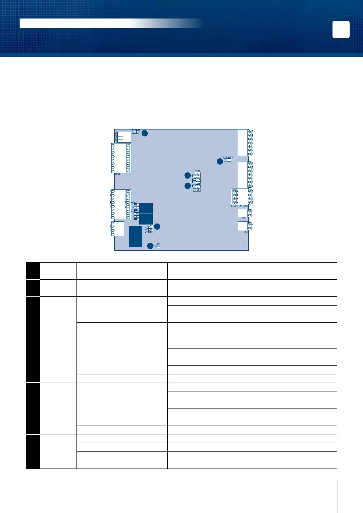
The ATRIUM 2-Door Controller has several status LEDs that are very useful to diagnose problems when using or
installing the ATRIUM system. Refer to the following picture for the emplacement of those LEDs on the ATRIUM
2-Door Controller. All LEDs are explained in the following pages.
READER 2
INPUTS
LOCAL
BUS
READER 1
BATT.
POWER
SUPPLY
BELL
DOOR 2
12V Z6 GND Z7 Z8
NO1 NC1
C2
NO2 NC2
GND Z9 Z10
12V Z1 GND Z2 Z3 GND Z4 Z5
AC22
2-Door Controller
1
2
3
4
5
6
1
2
1
ETHERNET ACT Green LED ashing: Data transmitted/received.
LNK Green LED: Ethernet network detected.
2
READERS #1 Green LED ashing: Data received from Reader #1.
#2 Green LED ashing: Data received from Reader #2.
3
GLOBAL STAT Flash once per second: Firmware is operating normally.
Flash rapidly: Firmware is upgrading.
Blink once per 3 seconds: Card enrollment mode.
DC IN DC IN Green LED: 2-Door Controller is powered properly.
Red LED: No primary power.
BATT BATT Green LED: Primary power present and battery charging.
Off LED: Primary power present and battery full.
Red LED: No battery or battery not properly connected.
Red LED ashing: Battery power is below 11.8Vdc.
BELL BELL Red LED: No bell/siren connected or short circuit.
4
SUPPLY AUX (12Vdc supply for readers
and inputs connections)
Green LED: Output power activated.
Off LED: Deactivated or in protection mode (short circuit).
VLK1/VLK2 Green LED: Output power activated.
Off LED: Deactivated or in protection mode (short circuit).
5
LOCAL BUS RX Green LED ashing: Data received on local bus.
TX Green LED ashing: Data transmitted on local bus.
6
RELAY LK1 Green LED: Door 1 Lock Relay is active/triggered.
LK2 Green LED: Door 2 Lock Relay is active/triggered.
RLY1 Green LED: Auxiliary Relay 1 is active/triggered.
RLY1 Green LED: Auxiliary Relay 2 is active/triggered.