9
9
Table 3
WELDING THICKNESS (mm) Ø ELECTRODE (mm)
1,5 ÷ 3
3 ÷ 5
5 ÷ 12
≥ 12
2
2,5
3,2
4
Table 4
Ø ELECTRODE (mm) CURRENT (A)
1,6
2
2,5
3,2
4
30 ÷ 60
40 ÷ 75
60 ÷ 110
95 ÷ 140
140 ÷ 190
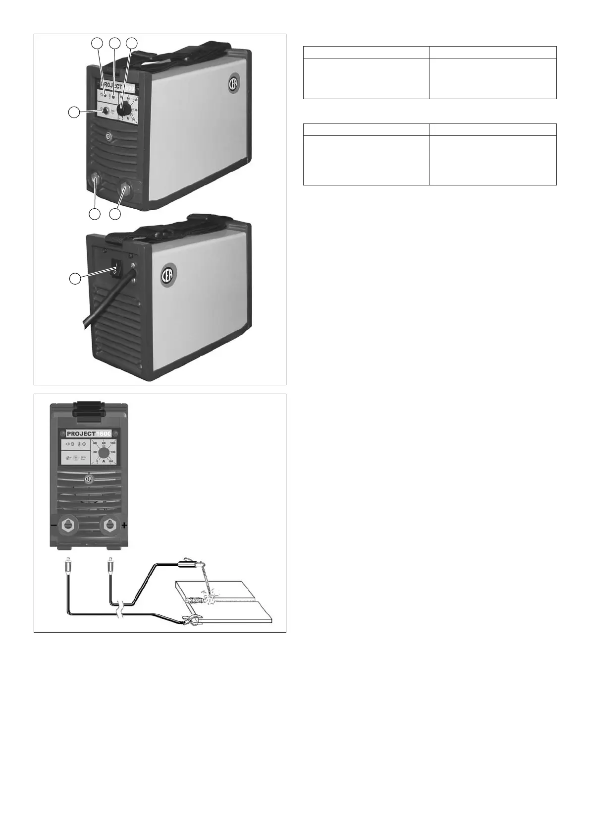
FIG. B
1 2 3
45
7
6
FIG. A
2000HA28
4) Start the welding machine by selecting position 1 on the
line switch (Pos. 7, Fig. A).
5) The white LED (Pos. 1, Fig. A) indicates that the welding
machine is powered and ready to work.
6) Carry out welding by moving the torch to the workpiece.
Strike the arc (press the electrode quickly against the met-
al and then lift it) to melt the electrode, the coating of which
forms a protective residue. Then continue welding by mov-
ing the electrode from left to right, inclining it by about 60°
compared with the metal in relation to the direction of weld-
ing.
PART TO BE WELDED
The part to be welded must always be connected to earth in or-
der to reduce electromagnetic emission. Much attention must
be afforded so that the earth connection of the part to be weld-
ed does not increase the risk of accident to the user or the risk
of damage to other electric equipment.
When it is necessary to connect the part to be welded to earth,
you should make a direct connection between the part and the
earth shaft. In those countries in which such a connection is
not allowed, connect the part to be welded to earth using sui-
table capacitors, in compliance with the national regulations.
WELDING PARAMETERS
Table 3 shows some general indications for the choice of elec-
trode, based on the thickness of the parts to be welded.
The values of current to use are shown in the table with the
respective electrodes for the welding of common steels and
low-grade alloys. These data have no absolute value and are
indicative data only. For a precise choice follow the instruc tions
provided by the electrode manufacturer.
The current to be used depends on the welding positions and
the type of joint, and it increases according to the thickness and
dimensions of the part.
The current intensity to be used for the different types of wel-
ding, within the field of regulation shown in table 4 is:
• High for plane, frontal plane and vertical upwards welding.
• Medium for overhead welding.
•
Low for vertical downwards welding and for joining small pre-
heated pieces.
A fairly approximate indication of the average current to use in
the welding of electrodes for ordinary steel is given by the fol-
lowing formula:
I = 50 x (Øe - 1)
Where:
I = intensity of the welding current
Øe = electrode diameter
Example:
For electrode diameter 4 mm
I = 50 x (4 -1) = 50 x 3 = 150A