50
3 4 5 6 7 13 141211109821
5
30
60 100 130
170
210
IT
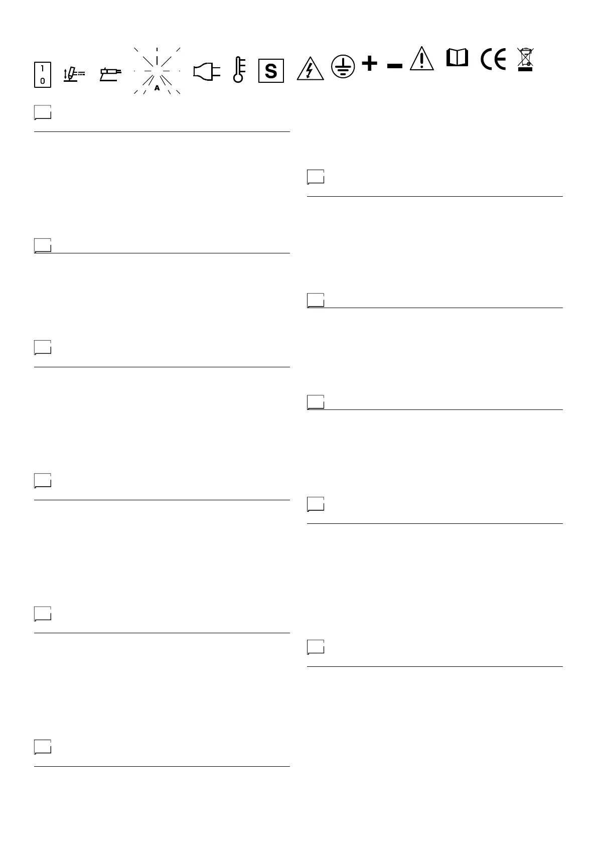
Significato dei simboli grafici
riportati sulla macchina
•1 Interruttore acceso/spento •2 Commutatore processo di saldatura •3
Scala della corrente di saldatura •4 Led bianco segnalazione presenza
alimentazione di rete •5 Led giallo a doppia funzione e protezione:
TERMOSTATO e OVERCURRENT •6 Impianto che può essere utilizzato
in ambienti con rischio accresciuto di scosse elettriche •7 Tensione
pericolosa •8 Terra di protezione •9 Attacco rapido polo positivo •10 Attacco
rapido polo negativo •11 Attenzione! •12 Prima di utilizzare l’impianto è
necessario leggere attentamente le istruzioni contenute in questo manuale
•13 Prodotto atto a circolare liberamente nella Comunità Europea •14
Smaltimento speciale
EN
Meaning of graphic symbols on machine
•1 On/off switch •2 Welding process switch •3 Welding current scale •4
White power-on LED •5 Yellow LED with dual function and protection:
THERMOSTAT and OVERCURRENT •6 System for use in environments
with increased risk of electroshock •7 Danger! high voltage •8 Grounding
protection •9 Positive pole snap-in connector •10 Negative pole snap-
in connector •11 Warning! •12 Before using the equipment you should
carefully read the instructions included in this manual •13 Product suitable
for free circulation in the European Community •14 Special disposal
FR
Interprétation des symboles graphiques
reportés sur la machine
•1 Interrupteur allum/teint •2 Commutateur procd de soudure •3 Echelle de
courant de soudure •4 LED blanche indiquant la présence d’alimentation
secteur •5 LED jaune à double fonction et protection: THERMOSTAT et
SURINTENSITÉ •6 Installation pouvant tre utilise dans des milieux avec
augmentation du risque de secousses lectriques •7 Tension dangereuse
•8 Terre de protection •9 Prise rapide ple positif •10 Prise rapide ple
negatif •11 Attention! •12 Avant dutiliser linstallation il est ncessaire de
lire avec attention les instructions qui se trouvent dans ce manuel •13
Produit pouvant circuler librement dans la Communauté Européenne •14
Elimination spéciale
DE
Bedeutung der grafischen
Symbole auf der Maschine
•1 Schalter EIN/AUS •2 Umschalter Schweissverfahren •3 Skale des
Schweisstromes •4 Weiße Led zeigt an, dass Netzstromversorgung
vorhanden ist •5 Gelbe LED mit Doppelfunktion und -schutz:
THERMOSTAT und ÜBERSTROM •6 Möglicher Gebrauch der Anlage
in Umgebung mit erhöhter Gefahr elektrischer Schläge •7 Gefährliche
Spannung •8 Schutzerde •9 Schnellanschluß Pluspol •10 Schnellanschluß
MInuspol •11 Achtung! •12 Vor der Anwendung der Anlage sind die
Gebrauchsanweisungen des vorliegenden Handbuches sorgfältig zu lesen
•13 Für den freien Warenverkehr in der EU zugelassenes Produkt •14
Sonderentsorgung
ES
Significado de los símbolos gráficos
referidos en la máquina
•1 Interruptor conectado/apagado •2 Comutador proceso de soldadura
•3 Escala corriente de soldadura •4 Led blanco señala la presencia de
alimentación en la red •5 Led amarillo con doble función y protección:
TERMOSTATO y OVERCURRENT •6 Instalacin que puede ser utilizada
en ambientes con grande riesgo de descargas elctricas •7 Tensin peligrosa
•8 Tierra de proteccin •9 Toma rpida polo positivo •10 Toma rpida polo
negativo •11 Atencin! •12 Antes de utilizar la instalacin, es necesario leer
atentamente las instrucciones contenidas en este manual •13 Producto
apto para circular libremente en la Comunidad Europea •14 Eliminación
especial
NL
Betekenis grafische symbolen op
het apparaat weergeven
•1 Onderbreker aan-uit •2 Comutator soldeeringsproces •3 Schaal van
de soldeerstroom •4 Witte LED duidt op aanwezigheid netvoeding •5
Gele LED met een dubbele functie en bescherming: THERMOSTAAT en
OVERSPANNING •6 Apparaat bruikbaar in ruimte met verhoogd risico voor
elektrische schokken •7 Gevaarlijke spanning •8 Beschermingsaarding •9
Snelkoppeling positieve pool •10 Snelkoppeling negatieve pool •11 Let op!
•12 Voordat de aansluiting in gebruik genomen wordt is het noodzakelijk om
aandachtig de gebruiksaanwijzing in deze handleiding te lezen •13 Produkt
mag overal binnen de EEG gebruikt worden •14 Speciale verwerking
PT
Significado dos símbolos gráfocos
existentes na máquina
•1 Interruptor ligado/desligado •2 Comutador processo de solda •3 Escala
da corrente de solda •4 Led branco sinalização presença alimentação de
rede •5 Led amarelo com função dupla e protecção: TERMÓSTATO e
OVERCURRENT •6 Equipamento que pode ser utilizado em ambientes
com risco acrescentado de choques eléctricos •7 Tensão perigosa •8
Terra de protecção •9 Encaixe rápido polo positivo •10 Encaixe rápido
polo negativo •11 Atenção! •12 Antes de usar a Instalação é necessário
ler atentamente as instruções contidas neste manual •13 Produto apto a
circular livremente na Comunidade Europeia •14 Vazão especial
SV
Förklaring av grafiska symboler på apparaten
•1 Strömbrytare på/avkopplad •2 Omkopplare svetsprocess •3 Skala
svetsström •4 Vit signaleringslampa för närvaro av nätspänning •5 Gul
signaleringslampa med dubbel funktion och skydd: TERMOSTAT och
ÖVERSPÄNNING •6 Apparat som kan användas i lokaler med förhöjd
risk för elstötar •7 Farlig spänning •8 Skyddsjord •9 Snabbkoppling pluspol
•10 Snabbkoppling minuspol •11 Observera! •12 Innan ibruktagandet av
anläggningen är det viktigt att uppmärksamt läsa instruktionerna i denna
manual •13 Produkt som får cirkulera fritt i EU •14 Specialavfall
FI
Laitteessa olevien symbolien selitykset
•1 Kynniss/sammutettu -katkaisija •2 Hitsaustyypin valitsin •3 Hitsausvirran
asteikko •4 Virran valkoinen LED-valo •5 Kahden toiminnon ja suojauksen
keltainen LED-valo: TERMOSTAATTI ja YLIVIRTA •6 Laitetta voidaan
kytt tiloissa, joissa on korkea shkiskujen vaara •7 Vaarallinen jnnite •8
Maadoitussuoja •9 Pikaliittimen positiivinen •10 Pikaliittimen negatiivinen
•11 Huomio! •12 Ennen laitteen kyttnottoa on trke lukea huolellisesti
tmn kyttoppaan sisltmt ohjeet •13 Produkt som kan sirkulere fritt i den
Europeiske Unionen •14 Erikoissäännösten mukainen hävittäminen
EL
Επεξηγήσεις των συμβόλων που
υπάρχουν στη μηχανή
•1 / •2
•3 •4
LED •5 LED
: •6
•7
•8 •9 •10
•11 ! •12
, ,
•13 ú
ú •14
RU
Значение графических символов
на сварочном аппарате
•1 •2
•3 •4
•5
: •6
,
•7 •8
•9 •10
•11 ! •12
, •13 ,
•14